Crank-slider-driven swing mirror mechanism

A crank slider and adjustment mechanism technology, applied in the direction of optical components, optics, instruments, etc., can solve the problem of high rotation accuracy and dynamic performance of torque motors, difficulty in overcoming the friction and influence of return springs, and affecting the adjustment of yaw angle Accuracy and other issues, to achieve the effect of low noise, simple structure, large adjustment accuracy

Active Publication Date: 2015-11-25
TONGJI UNIV
View PDF9 Cites 17 Cited by
  • Summary
  • Abstract
  • Description
  • Claims
  • Application Information

AI Technical Summary

Problems solved by technology

[0003] In the prior technology (Sun Jianfeng and other patents, application number: 200410024986.2, application date October 2004 "High-precision dynamic and static measurement device for inter-satellite laser communication terminals"), the torque motor is used to directly couple the rotating shaft to realize the deflection of the optical element, thereby Angle adjustment is realized, but the mechanical system has high requirements on the rotation accuracy and dynamic performance of the torque motor, and the mechanical error is relatively large
[0004] In the prior technology (Patent of Li Anhu et al., application number: 200510026553.5, application date June 2005 "Double optical wedge beam deflection mechanical device"), a linear motor direct jacking drive method is proposed, which belongs to the variable load system during motion, not only It is difficult to guarantee the control accuracy, and it is difficult to overcome the friction and influence generated by the return spring and the ejector rod during the movement
[0005] In the prior technology (Patent of Li Anhu et al., application number: 201010588924.X, application date December 2010 "Scanning Device for Swinging Optical Wedge"

Method used


Image

  • Crank-slider-driven swing mirror mechanism
  • Crank-slider-driven swing mirror mechanism
  • Crank-slider-driven swing mirror mechanism

Examples


Embodiment 1

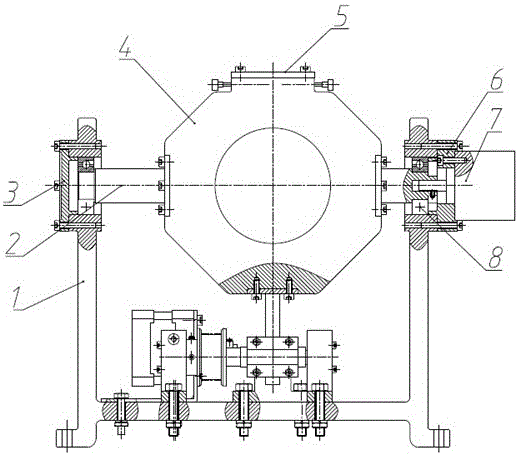
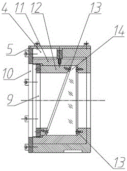
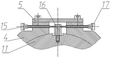
[0033] see Figure 1-Figure 6 as shown, figure 1 It is the overall structural diagram of the pendulum mirror mechanism driven by the slider crank of the present invention, figure 2 It is the structural diagram of the pendulum mirror and the picture frame assembly of the present invention, image 3 It is a structural diagram of the adjustment mechanism for the main section of the pendulum mirror of the present invention, Figure 4 It is a structural diagram of the motor and transmission mechanism of the present invention, Figure 5 It is a partial enlarged view of the crankshaft support structure of the motor and transmission mechanism of the present invention, Image 6 For the motor and the transmission mechanism of the present invention swing the slider part of the guide rod.

[0034] see figure 2First, put the small-diameter end of the nylon spacer 13 into the hole of the shaft shoulder of the inner lens frame 11 and the wedge-shaped pressure block 12, the pendulum mi...


PUM


Abstract

The invention relates to a crank-slider-driven swing mirror mechanism, which comprises a swing mirror and mirror frame assembly, a swing mirror principal section adjusting mechanism, a rotary encoder, a motor and transmission mechanism, and a machine frame. The swing mirror and mirror frame assembly comprises a swing mirror, a nylon cushion block, a wedge-shaped pressing block, a threaded check ring, an inner mirror frame, an outer mirror frame, an outer mirror frame end cap, an outer mirror frame upper cover plate, a rotating half shaft, a first bearing end cap, a second bearing end cap and a machine frame antifriction bearing. The swing mirror principal section adjusting mechanism comprises an inner mirror frame adjusting block, a first adjusting screw rod and a second adjusting screw rod. The motor and transmission mechanism comprises a motor, a motor bracket, a synchronous belt, a small pulley, a large pulley, a horizontal sliding block, a horizontal guide rail, a hinge bar, an L-shaped connecting block, a connecting rod, a crankshaft bearing, a connecting rod cap, a crankshaft, a crankshaft bearing end cap and a crankshaft antifriction bearing. According to the technical scheme of the invention, the small-angle deflection movement of the swing mirror is converted into the long-distance rectilinear movement of a slider by the crank-slider-driven swing mirror mechanism. In this way, the high-precision deflection movement of the swing mirror can be realized based on the low-precision rectilinear movement of the slider, and the requirement on the control accuracy is lowered.

Description

technical field [0001] The invention relates to a swing mirror mechanism driven by a crank slider, which can be used for high-precision angle scanning and displacement tracking in the field of precision engineering. Background technique [0002] The pendulum mirror mechanism has a wide range of applications in the field of precision photoelectric tracking. It can realize high-precision optical tracking, scanning, alignment, measurement and compensation of dynamic errors, etc. [0003] In the prior technology (Sun Jianfeng and other patents, application number: 200410024986.2, application date October 2004 "High-precision dynamic and static measurement device for inter-satellite laser communication terminals"), the torque motor is used to directly couple the rotating shaft to realize the deflection of the optical element, thereby Angle adjustment is realized, but the mechanical system has high requirements on the rotation accuracy and dynamic performance of the torque motor,...

Claims


Application Information

Patent Timeline
IPC IPC(8): G02B26/10
Inventor 李安虎孙万松
Owner TONGJI UNIV
Why Eureka
Try Eureka