A shielding plate and reaction chamber

A reaction chamber and shielding technology is applied in the field of shielding discs and reaction chambers to achieve the effects of improving economic benefits and reducing chamber costs

Active Publication Date: 2018-05-08
BEIJING NAURA MICROELECTRONICS EQUIP CO LTD
View PDF7 Cites 0 Cited by
  • Summary
  • Abstract
  • Description
  • Claims
  • Application Information

AI Technical Summary

Problems solved by technology

[0006] The present invention aims to solve the technical problems existing in the prior art, and provides a shielding plate and a reaction chamber. The size of the shielding plate is small when stored, so there is no need to set up a garage in the reaction chamber to place the shielding plate. Thus, the chamber cost of the reaction chamber can be reduced, which in turn can improve economic efficiency

Method used


Image

  • A shielding plate and reaction chamber
  • A shielding plate and reaction chamber
  • A shielding plate and reaction chamber

Examples


Embodiment Construction

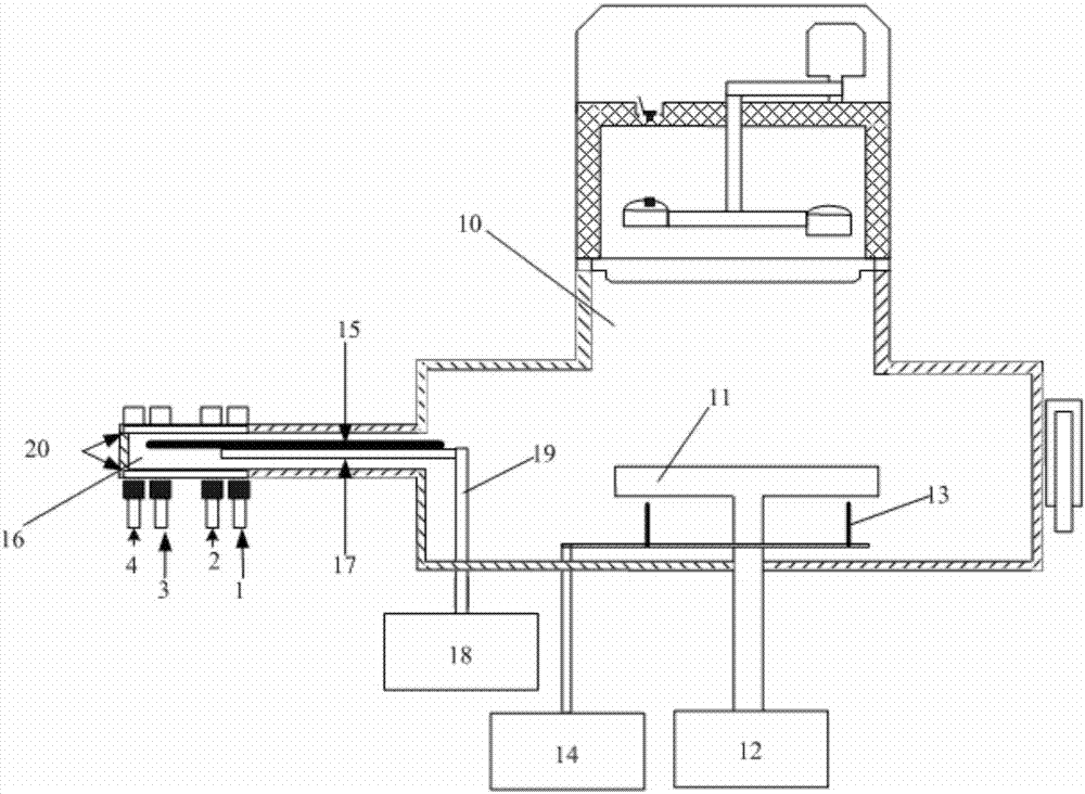
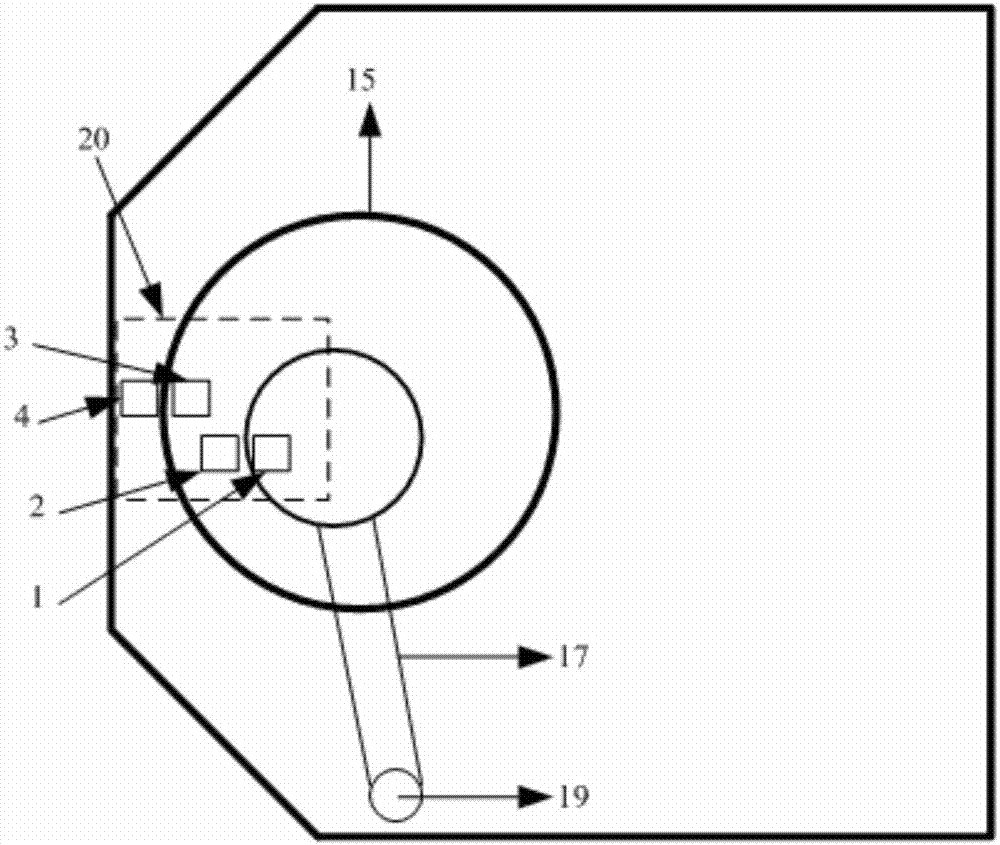
[0030] In order for those skilled in the art to better understand the technical solution of the present invention, the shielding plate and the reaction chamber provided by the present invention will be described in detail below with reference to the accompanying drawings.

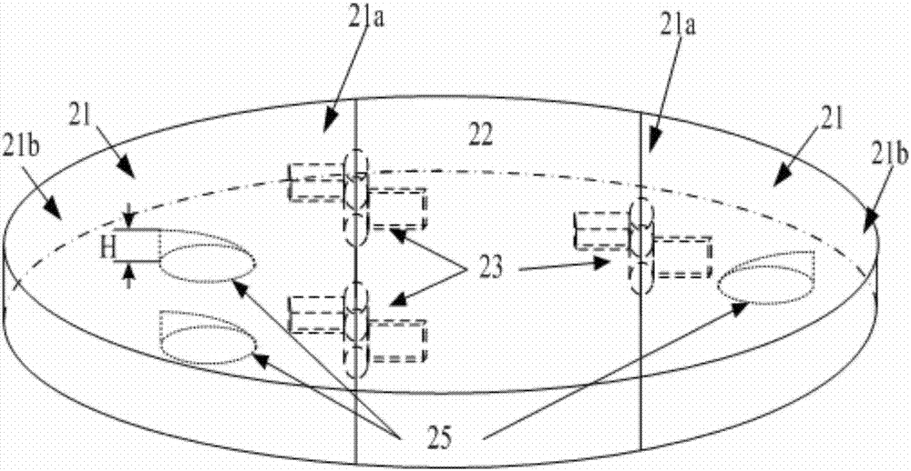
[0031] image 3A schematic diagram of the structure of the shielding plate in use provided by the embodiment of the present invention. Figure 4 for image 3 Bottom view of the shielding disk shown. Figure 5 It is a front view of the shielding disk provided by the embodiment of the present invention when it is stored. Please also refer to image 3 , Figure 4 and Figure 5 , the shielding disk provided in this embodiment includes a rotating subsection 21 and a body 22 . Wherein, the rotating subsection 21 includes a fixed end 21a and a movable end 21b, the fixed end 21a is connected with the peripheral wall of the body 22, and the rotating subsection 21 is arranged along the circumferential direction...


PUM


Abstract

The invention provides a shielding plate and a reaction chamber. The shielding plate includes a rotating part and a body. The rotating part includes a fixed end and a movable end. Orientation setting, the movable end of the rotating part is located at the original position under the action of its own gravity, and the original position is defined as the position of the movable end when the angle between the lower surface of the rotating part and the lower surface of the body is a preset obtuse angle, When using the shielding disk to shield the object to be shielded, the movable end of the rotating section is lifted from the original position to the preset highest position, so that the rotating section and the main body form a shielding disk that can shield the object to be shielded. The shielding plate provided by the present invention has a small size during storage, so there is no need to set up a garage in the reaction chamber to place the shielding plate, thereby reducing the chamber cost of the reaction chamber and improving economic benefits.

Description

technical field [0001] The invention belongs to the technical field of semiconductor equipment manufacturing, and in particular relates to a shielding plate and a reaction chamber. Background technique [0002] Physical vapor deposition (Physical Vapor Deposition, hereinafter referred to as PVD) equipment is a relatively widely used plasma processing equipment, which is mainly used to deposit thin films on the surface of workpieces to be processed such as substrates. PVD methods include vacuum evaporation, sputtering coating, and arc plasma coating, and, so far, PVD methods can not only deposit metal films, but also deposit alloy films, compound films, ceramic films, semiconductor films, etc. [0003] In practical applications, usually before the deposition process is performed, it is necessary to perform a cleaning process on the target exposed to the atmosphere or out of service for a period of time (that is, to clean the oxide or other impurities formed on the surface of ...

Claims


Application Information

Patent Timeline
Patent Type & Authority Patents(China)
IPC IPC(8): H01L21/67H01L21/02
Inventor 沈围
Owner BEIJING NAURA MICROELECTRONICS EQUIP CO LTD
Why Eureka
Try Eureka