
A dielectric resonator antenna array for generating vortex radio waves

A technology for dielectric resonators and antenna arrays, applied in antenna arrays, antennas, slot antennas, etc., can solve the problems of high loss and difficult fabrication, and achieve the effect of easy fabrication and reduced loss

Active Publication Date: 2018-03-27
HUAZHONG UNIV OF SCI & TECH
View PDF3 Cites 0 Cited by
  • Summary
  • Abstract
  • Description
  • Claims
  • Application Information

AI Technical Summary

Problems solved by technology

[0004] Aiming at the above defects or improvement needs of the prior art, the present invention provides a dielectric resonator antenna array for generating vortex electric waves. Difficult technical issues

Method used


Image

  • A dielectric resonator antenna array for generating vortex radio waves
  • A dielectric resonator antenna array for generating vortex radio waves
  • A dielectric resonator antenna array for generating vortex radio waves

Examples


Embodiment Construction

[0027] In order to make the object, technical solution and advantages of the present invention clearer, the present invention will be further described in detail below in conjunction with the accompanying drawings and embodiments. It should be understood that the specific embodiments described here are only used to explain the present invention, not to limit the present invention. In addition, the technical features involved in the various embodiments of the present invention described below can be combined with each other as long as they do not constitute a conflict with each other.

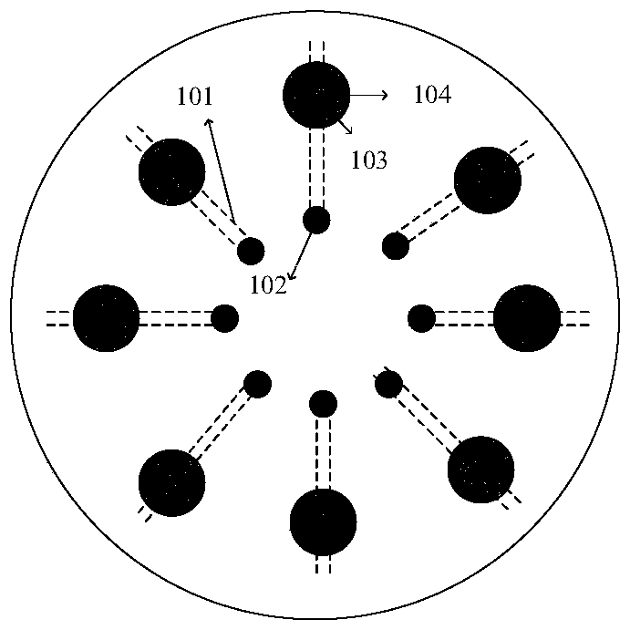
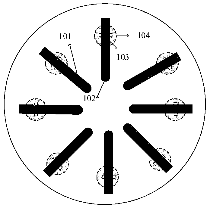
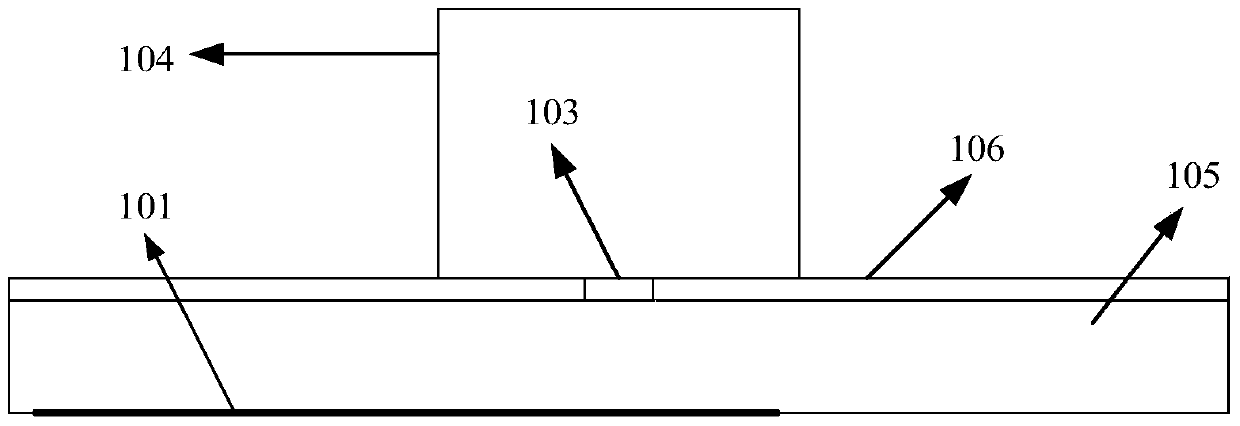
[0028] As shown in Fig. 1 (A), (B), (C), the dielectric resonator antenna array that the present invention produces vortex electric wave comprises a plurality of microstrip lines 101, coaxial feed port 102, a plurality of rectangular slots 103, A plurality of dielectric resonator antennas 104 (the number of which is N, where N is a positive integer greater than or equal to 4), a dielectric subst...


PUM


Abstract

The invention discloses a dielectric resonator antenna array for generating vortex electric waves. The antenna array is composed of N dielectric resonator antennas evenly arranged on the circular printed board (ground plane side), and N rectangular slots are opened at the connection between the dielectric resonator antenna and the ground plane; There are N uniformly distributed microstrip lines, N≥4, one end of the microstrip line is fed by the coaxial line, and the other end is fed by the dielectric resonator antenna through the coupling with the rectangular slot. Thus, N‑1 modes of vortex electric waves (OAM waves) are generated. The dielectric resonator antenna array of the invention has the advantages of high gain, low loss and high broadband.

Description

technical field [0001] The invention belongs to the technical field of wireless communication, and more specifically relates to a dielectric resonator antenna array for generating vortex electric waves. Background technique [0002] Electromagnetic waves can carry both linear and angular momentum, and there are two types of angular momentum: (1) spin angular momentum (SAM) and (2) orbital angular momentum (OAM). Among them, there are two modes of spin angular momentum: left-handed circular polarization and right-handed circular polarization, both of which have been widely used in communication systems to improve communication capacity. Orbital angular momentum is a relatively new concept, which was discovered by Allen et al. in 1992, see Allen, L., et al., "Orbital angular momentum of light and the transformation of Laguerre-Gaussian laser modes." Phys Rev A, 1992.45(11): p.8185-8189. Through the study of Orbital Angular Momentum (OAM), it is found that Orbital Angular Mom...

Claims


Application Information

Patent Timeline
Patent Type & Authority Patents(China)
IPC IPC(8): H01Q1/36H01Q13/10H01Q21/00
Inventor 张思贤桂良启刘丹丹
Owner HUAZHONG UNIV OF SCI & TECH
Learn More