Motor of stator and rotor split type for sewing machine

A sewing machine, split technology, applied in the direction of electromechanical devices, electrical components, electric components, etc., can solve the problem that the stator or rotor cannot be used as a separate component, the length and size of the motor vary greatly, and the size of the motor shaft is difficult to ensure. Achieve the effect of small axial size, space saving and production cost reduction

Active Publication Date: 2015-11-25
JIANGSUSNGQI GROUP
View PDF5 Cites 0 Cited by
  • Summary
  • Abstract
  • Description
  • Claims
  • Application Information

AI Technical Summary

Problems solved by technology

[0006] 1. The motor as a whole is used as a part of the sewing machine, and the stator or rotor cannot be used as a separate component
[0007] 2. The main shaft of the sewing machine and the motor shaft are connected by a coupling, so that the axial size of the sewing machine is large and will take up more space
In this way, there will be a high temperature rise, uneven thickness of the stator silicon steel sheet, resulting in a large change in the length and size of the motor, and it is difficult to ensure the size of the motor output shaft, and the front and rear end covers will be affected by the unevenness of the stator core. Parallel leads to non-parallel; it also leads to more bearing noise
[0009] 4. The encoder and grating components are separate components, and there is no mechanical connection between them
In this way, during the long-term operation of the motor, the bearing will be damaged due to the life of the bearing grease or external force, which will shorten the service life of the motor due to the damage of the bearing, and will also cause bearing noise during the normal assembly process.

Method used


Image

  • Motor of stator and rotor split type for sewing machine
  • Motor of stator and rotor split type for sewing machine
  • Motor of stator and rotor split type for sewing machine

Examples


Embodiment Construction

[0063] The present invention will be further described in detail below in conjunction with the accompanying drawings and specific preferred embodiments.

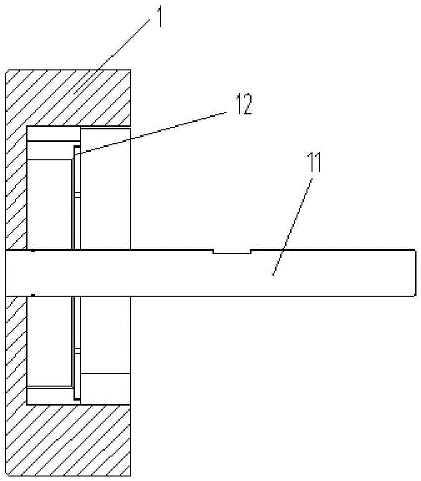
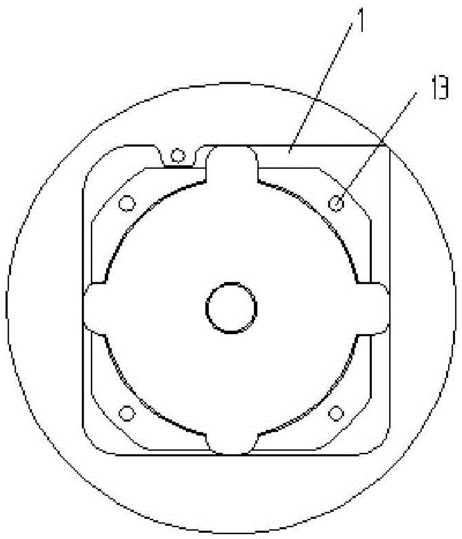
[0064] Sewing machines for household or industrial use, including sewing machine heads1, such as figure 2 and image 3 As shown, the center of the sewing machine head 1 is provided with a sewing machine main shaft 11, and the right end surface of the sewing machine head 1 is provided with a notch 12 and several stator mounting threaded holes 13.

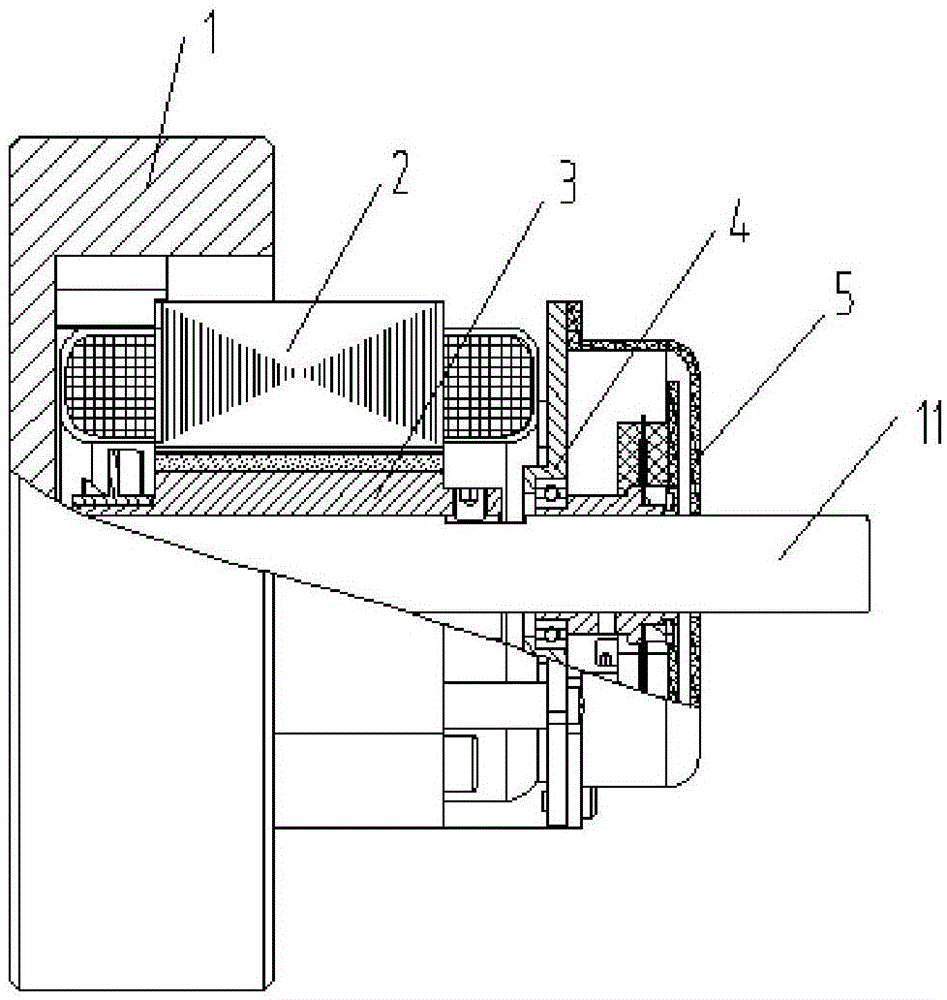
[0065] Such as figure 1 As shown, a stator and rotor split motor for a sewing machine includes a stator 2, a rotor 3, an integrated encoder 4 and a rear cover 5.

[0066] The center of above-mentioned rotor 3, integrated encoder 4 and back cover 5 is all provided with axial central hole 31, and the diameter of this axial central hole 31 is greater than the outer diameter of sewing machine main shaft 11; Rotor 3, integrated encoder 4 and rear The cover 5 is coaxially fixed and s...


PUM


Abstract

The invention discloses a motor of a stator and rotor split type for a sewing machine, and the motor is connected with the head of the sewing machine. The motor comprises a stator, a rotor, an integrated coder, and a rear cover, wherein the rotor is a hollow shaft. The rotor, the integrated coder and the rear cover are sequentially fixed on a sewing machine main shaft in the head of the sewing machine in a coaxial and sleeved manner. The stator is fixedly connected with the head of the sewing machine. The integrated coder is connected with a needle rod of the sewing machine, and can control the angle of the needle rod of the sewing machine. A coder seat is provided with a coder installation column with adjustable height. An optical grating assembly comprises an optical grating support, an optical grating sheet, an optical grating pressure ring, and a clamping spring, wherein the optical grating support is coaxially disposed on the sewing machine main shaft in a sleeved manner, and can be rotated and fixed. After the above structure is employed, the motor is small in axial size, can save the space, is small in load inertia, and is high in sewing speed. The stator or the rotor can serve as an independent part of the sewing machine, and the motor is small in temperature rise, and is low in noise. Meanwhile, the angle of the needle rod of the sewing machine can be controlled according to the needs, and the motor is convenient in operation, and is high in sewing precision.

Description

technical field [0001] The invention relates to a driving part of sewing equipment, in particular to a stator and rotor split motor for sewing machines. Background technique [0002] At present, the motor structure mainly has the following two types: [0003] The first type: The motor includes bearings, front end cover, rear end cover, solid shaft, encoder and grating assembly. The stator is shrunk into the casing, and the front end cover and the rear end cover are fitted through the casing and then fixed with screws. The casing needs to be stretched and deformed from the aluminum rod during the processing process, and aging treatment needs to be carried out in a constant temperature environment. Before the casing is made into a profile factory, it needs to be sandblasted and anodized; therefore, in the process from the aluminum rod to the casing In the process, it needs to consume a lot of electric energy, which increases carbon emissions; after the casing is formed, in o...

Claims


Application Information

Patent Timeline
Patent Type & Authority Applications(China)
IPC IPC(8): H02K1/06H02K1/12H02K1/22H02K5/16H02K11/00H02K9/04H02K7/14
Inventor 印光宇
Owner JIANGSUSNGQI GROUP
Why Eureka
Try Eureka