Refrigeration device comprising an evaporator

A technology for refrigeration appliances and evaporators, applied in evaporators/condensers, refrigerators, refrigeration components, etc., can solve problems such as refrigerant noise, and achieve the effect of noise reduction and less material consumption

Inactive Publication Date: 2015-11-25
BSH BOSCH & SIEMENS HAUSGERAETE GMBH
View PDF7 Cites 0 Cited by
  • Summary
  • Abstract
  • Description
  • Claims
  • Application Information

AI Technical Summary

Problems solved by technology

Therefore, the flow of r

Method used


Image

  • Refrigeration device comprising an evaporator
  • Refrigeration device comprising an evaporator
  • Refrigeration device comprising an evaporator

Examples


Embodiment Construction

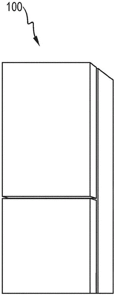
[0045] figure 1 A refrigeration appliance 100 in the form of a refrigerator is shown having an upper refrigerator door and a lower refrigerator door. Refrigerators are used, for example, to keep food cold and comprise a refrigerant circuit with an evaporator, a compressor, a condenser and a throttling device. An evaporator is a heat exchanger in which, after expansion, liquid refrigerant is evaporated by absorbing heat from the medium to be cooled, which is the air inside the refrigerator.

[0046] The compressor is the mechanically operated component that receives refrigerant vapor from the evaporator and injects the refrigerant vapor at higher pressure to the condenser. Condensers are heat exchangers in which evaporated refrigerant, after compression, is condensed by dissipating heat to an external cooling medium, which is ambient air. A throttling device is a device used to continuously reduce pressure by constricting the cross-section.

[0047] A refrigerant is a fluid ...


PUM


Abstract

The present invention relates to a refrigeration device having an evaporator (103) for evaporating a refrigerant, which evaporator comprises an inlet pipe (105) for the admission of the refrigerant, in which inlet pipe there is formed a pipe region (107), which has a first flow cross section, and a constriction region (109), which has a second flow cross section smaller than the first flow cross section, and to a method for producing an evaporator of said type.

Description

technical field [0001] The invention relates to a refrigeration appliance with an evaporator. Background technique [0002] At the point where the refrigerant is injected into the evaporator of the refrigeration appliance, the refrigerant is injected through the throttling device into the inlet pipe of the evaporator, which inlet pipe has a much larger inner diameter than at the opening of the throttling device. Therefore, the flow of refrigerant generates noise. Contents of the invention [0003] The object of the present invention is to propose a refrigeration appliance in which the noise generated when refrigerant is injected into the evaporator is reduced. [0004] This object is achieved by the subject matter having the features set forth in the independent claims. Advantageous embodiments of the invention are the subject matter of the figures, the description and the dependent claims. [0005] According to one aspect of the invention, this object is achieved by a ...

Claims


Application Information

Patent Timeline
IPC IPC(8): F25B39/02
CPCF25B39/02F25B2500/12F25B2500/18F28D2021/0064F28F9/026F28F2265/28B23P15/26F25B39/00
Inventor B·施勒格尔A·福格尔R·梅纳D·米齐科H·莫赫
Owner BSH BOSCH & SIEMENS HAUSGERAETE GMBH
Why Eureka
Try Eureka