
Swing type feeding device

A feeding device and swing type technology, applied in the field of swing feeding device, can solve the problems such as the difficulty and complexity of the control of width, thickness, dimensional accuracy, plate shape and surface quality, complex and huge rolling mill equipment, and large rolling pressure, etc. Simple structure, low cost and stable feeding

Inactive Publication Date: 2015-12-02
TIANJIN CHAOMAI TECH DEV CO LTD
View PDF0 Cites 6 Cited by
  • Summary
  • Abstract
  • Description
  • Claims
  • Application Information

AI Technical Summary

Problems solved by technology

(3) Due to the large width-to-thickness ratio and surface area, the rolling pressure in production is very high, which can reach millions to tens of millions of Newtons. Therefore, the rolling mill equipment is complex and huge, and the product width, thickness, dimensional accuracy and plate shape and The control of surface quality has also become very difficult and complicated
At present, the stamping production of sheet metal adopts automatic feeding device. The common feeding device is a set of feeding rollers to realize the feeding of the sheet material. Generally, the ratchet mechanism and the overrunning clutch are used as the intermittent transmission mechanism to realize the intermittent feeding of the sheet material. However, this The structure is more complicated and the cost is higher

Method used


Image

  • Swing type feeding device
  • Swing type feeding device

Examples


Embodiment Construction

[0013] The present invention will be further described in detail below in conjunction with the accompanying drawings and examples. The following examples are explanations of the present invention and the present invention is not limited to the following examples.

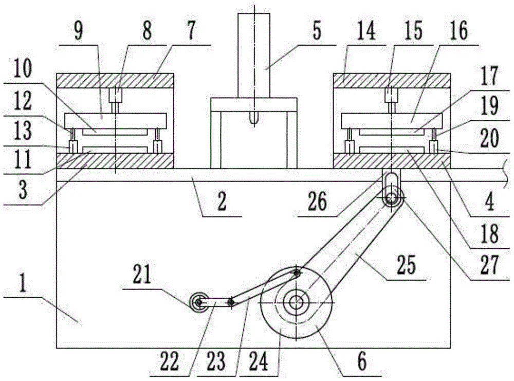
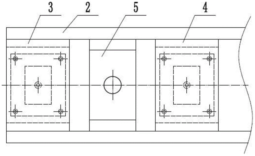
[0014] Such as figure 1 and figure 2 As shown, a swing feeding device includes a base 1, a slide rail 2, a clamping mechanism 3, a feeding mechanism 4, a stamping mechanism 5, and a swing driving mechanism 6. The clamping mechanism 3 realizes the clamping and loosening of one end of the plate. Open, the feeding mechanism 4 realizes the intermittent feeding of the plate, the swing driving mechanism 6 realizes the back and forth movement of the feeding mechanism, and the stamping mechanism 5 realizes the stamping process of the plate. The clamping mechanism 3 is arranged on the left side of the base 1, the slide rail 2 is horizontally arranged on the base 1, the feeding mechanism 4 can slide left and right and is ar...


PUM


Abstract

The invention provides a swing type feeding device and belongs to the technical field of machining. The swing type feeding device comprises a material clamping mechanism, a feeding mechanism and a swing drive mechanism. The feeding mechanism can be arranged on a sliding rail in a left-right sliding mode. The lower end of a material clamping air cylinder of the material clamping mechanism is connected with an upper material clamping supporting plate. An upper material clamping plate is arranged at the lower end of the upper material clamping supporting plate. A lower material clamping plate is arranged on a material clamping supporting seat. An upper feed material clamping plate of the feeding mechanism is arranged at the lower end of an upper fed material supporting plate. A lower fed material clamping plate is arranged on a material feeding supporting seat. A connection support of the swing drive mechanism is arranged at the lower end of the material feeding supporting seat. One end of a swing arm is hinged to the connection support, and the other end of the swing arm is arranged on a rotary table. The rotary table is arranged on a seat in a rotating mode. One end of a connection rod is hinged to the rotary table, the other end of the connection rod is hinged to one end of a rocking bar, and the other end of the rocking bar is connected with a drive motor. By means of the swing type feeding device, intermittent feeding of panels is achieved, and the swing type feeding device is simple in structure, low in cost, stable in feeding and good in reliability.

Description

technical field [0001] The invention relates to the technical field of mechanical processing, in particular to a swing feeding device. Background technique [0002] Plates mostly refer to metal plates made of forging, rolling or casting. Divided into thin plate, medium plate, thick plate, extra thick plate, usually made into flat rectangular building material plates of standard size. The shape of the plate product is flat, the ratio of width to thickness is large, and the surface area per unit volume is also large. This shape feature brings its characteristics in use: (1) The surface area is large, so the ability to contain and cover is strong. It is used in chemical industry, containers, construction, and metal products. (2) Can be arbitrarily cut, bent, stamped, welded, and made into various product components. It is flexible and convenient to use, and occupies an extremely important position in the departments of automobile, aviation, shipbuilding and tractor manufacturi...

Claims


Application Information

Patent Timeline
IPC IPC(8): B21D43/11
Inventor 谭博文
Owner TIANJIN CHAOMAI TECH DEV CO LTD
Learn More