Raw gas separation system

A separation system and crude gas technology, applied in the field of coal chemical industry, can solve the problems of poor dust and tar removal effect, high cost, complex structure of separation device, etc., to reduce temperature, improve efficiency and heat exchange efficiency, and increase contact area Effect

Active Publication Date: 2015-12-02
SHAANXI COAL & CHEM IND GRP SHENMU TIANYUAN CHEM IND +1
View PDF5 Cites 4 Cited by
  • Summary
  • Abstract
  • Description
  • Claims
  • Application Information

AI Technical Summary

Problems solved by technology

[0005] For this reason, the technical problem to be solved by the present invention is that the structure of the separating device of crude gas dust and tar in the prior art is complicated, the effect of dust removal and tar is not good, the cost is high, and the maintenance is inconvenient. A raw gas separation system with excellent tar effect, simple structure, low cost and convenient maintenance

Method used


Image

  • Raw gas separation system
  • Raw gas separation system

Examples


Embodiment 1

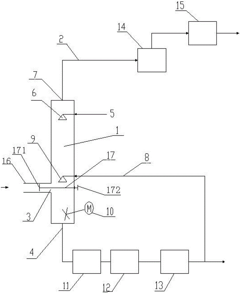
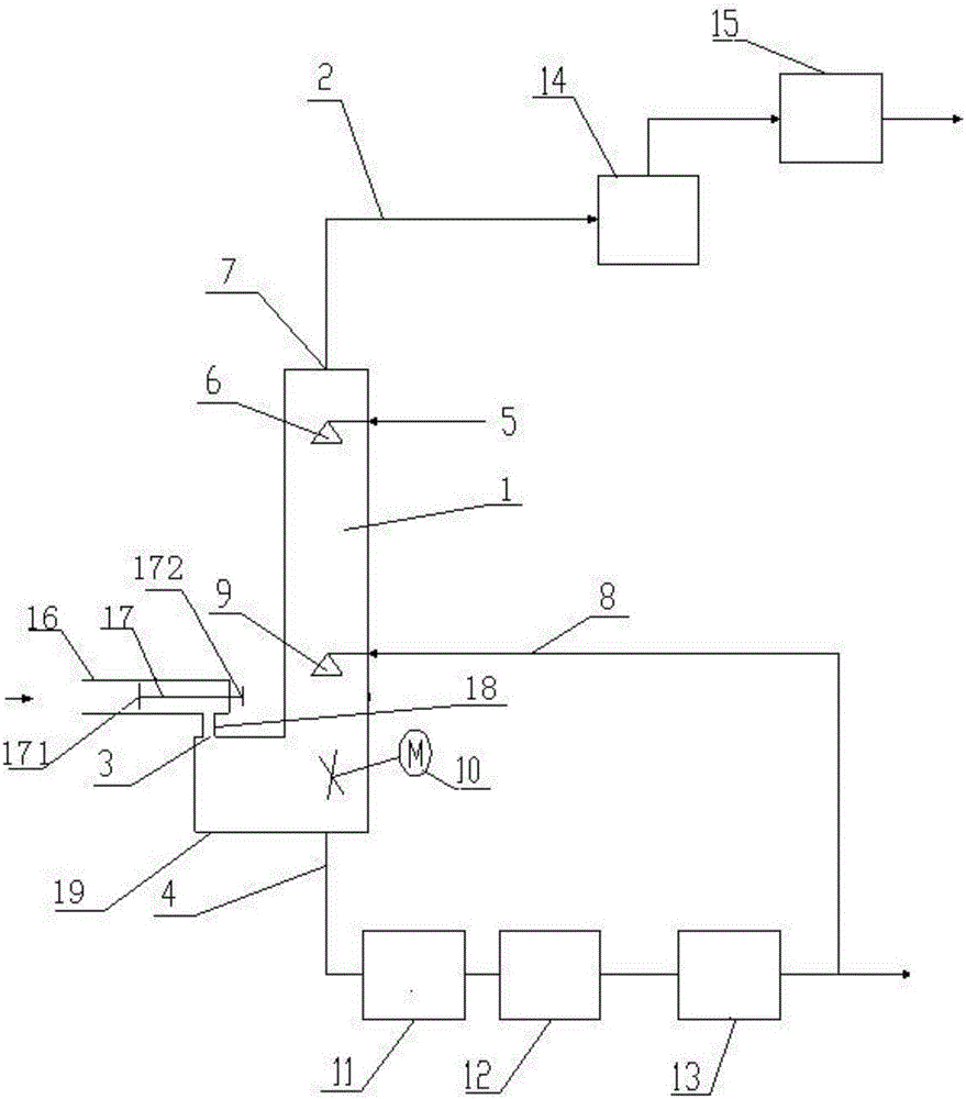
[0039] Such as figure 1 A crude gas separation system shown includes a tower body 1, a gas outlet pipe 2 is connected to the top of the tower body 1, a crude gas inlet 3 is provided at the bottom of the tower body 1, and a crude gas inlet 3 is provided at the bottom of the tower body 1. A tar discharge pipe 4 is connected, a first tar spray pipe 5 is connected on the top of the tower body 1, and a first tar spray nozzle 6 extending into the inside of the tower body 1 is connected on the first tar spray pipe 5, The first tar spray nozzle 6 is located below the gas outlet 7 of the gas outlet pipe 2; the second tar spray pipe 8 is connected in the middle of the tower body 1, and the second tar spray pipe 8 is connected with a The second tar sprayer 9 inside the tower body 1, the second tar sprayer 9 is located below the first tar sprayer 6; the length between the first tar sprayer 6 and the top of the tower body 1 is 1 / 10-2 / 9 of the total length of the tower body 1; the length b...


PUM

PropertyMeasurementUnit
densityaaaaaaaaaa
densityaaaaaaaaaa

Abstract

The invention discloses a raw gas separation system which comprises a tower body, wherein a gas outlet pipe is connected with the top of the tower body; a raw gas inlet is formed in the lower part of the tower body; a tar discharging pipe is connected with the bottom of the tower body; a first tar spraying pipe is connected with the upper part of the tower body; a first tar nozzle which extends into the tower body and is positioned below the gas outlet of the gas outlet pipe is connected onto the first tar spraying pipe; a second tar spraying pipe is connected with the middle of the tower body; a second tar nozzle which extends into the tower body is connected onto the second tar spraying pipe, and positioned below the first tar nozzle; the ratio of the length between the first tar nozzle and the top of the tower body to the total length of the tower body is (1:10)-(2:9); the ratio of the length between the second tar nozzle and the top of the tower body to the total length of the tower body is (1:2)-(2:3); the ratio of the length between the raw gas inlet and the top of the tower body to the total length of the tower body is (2:3)-(4:5). Through adoption of the raw gas separation system, the problems that the conventional oil-gas separation device is complex in structure, the effect of removing dust and tar is poor, the cost is high, and maintenance is inconvenient can be solved.

Description

technical field [0001] The invention belongs to the field of coal chemical industry, and in particular relates to a crude gas separation system. Background technique [0002] my country is a country short of oil and gas but relatively rich in coal resources, but coal has not been well utilized as an alternative energy source with abundant reserves. With the rapid development of the economy, China's energy demand has maintained a high-speed growth, and the domestic demand for crude oil has increased year by year. The import volume of crude oil has continuously set new historical records, and the domestic oil production is far from meeting the requirements of the rapid development of the domestic economy. Therefore, vigorously developing the coal chemical industry and replacing petrochemical products with coal chemical products has become an inevitable choice for my country's energy strategy. [0003] At present, pulverized coal carbonization and pyrolysis upgrading has becom...

Claims


Application Information

Patent Timeline
Patent Type & Authority Applications(China)
IPC IPC(8): C10K1/02C10K1/16C10K1/18C10K1/04
Inventor 王守峰山秀丽李万飞贺鑫平常景泉王淑岩吕子胜李锦涛何战柱
Owner SHAANXI COAL & CHEM IND GRP SHENMU TIANYUAN CHEM IND
Why Eureka
Try Eureka