Shaft type connecting rod transmission system and opposed piston engine

A connecting rod transmission, opposed piston technology, applied in the direction of transmission, machine/engine, mechanical equipment, etc., can solve the problems of complex limit mechanism, mechanical wear and noise, left and right baffle impact, etc., to simplify the transmission system and Gas distribution system, reducing mechanical wear and noise, and the effect of compact overall structure

Active Publication Date: 2015-12-02
郑安庆
View PDF8 Cites 15 Cited by
  • Summary
  • Abstract
  • Description
  • Claims
  • Application Information

AI Technical Summary

Problems solved by technology

Its shortcoming is that, because the clutch internal tooth assembly inevitably swings during the movement process, the connecting rod also swings accordingly, so the connection between the connecting rod and the main working piston cannot be fixed, but only hinged, so it cannot be connected A sealing ring is set on the rod, so that the space between the back of the piston and the cylinder cannot be air-tight and cannot be used. The additional auxiliary piston, although the direct shaft drive is realized, the meshing of the transmission gear and the transmission rack is due to The swing of the inner tooth assembly is not reliable, and there are two abrupt steps on the arc-shaped convex edge of the rever

Method used


Image

  • Shaft type connecting rod transmission system and opposed piston engine
  • Shaft type connecting rod transmission system and opposed piston engine
  • Shaft type connecting rod transmission system and opposed piston engine

Examples


Embodiment 1

[0042] Figure 6 to Figure 9 Shown is a two-stroke dual opposed piston engine. Taking the axis of the main shaft 10 as the reference center, the piston close to the axis is called the "inner piston", and the piston farther from the axis than the "inner piston" is called the "outer piston". Similarly, the axial connecting rod fixedly connected to the "inner piston" is called the "inner axial connecting rod", and the axial connecting rod fixedly connected to the "outer piston" is called the "outer frame-shaped axial connecting rod".

[0043] Reference Image 6 , Figure 7 The opposed-piston engine of the present invention includes at least a pair of linear reciprocating units arranged on the planes on both sides of the axis of the main shaft 10, and the linear reciprocating body A includes an inner piston 51a and an outer piston 51b arranged in the cylinder 50. The axial connecting rod 40 includes an inner axial connecting rod 40a whose inner end is fixedly connected to the inner ...

Embodiment 2

[0054] Picture 9 with Picture 10 Shown is a four-stroke opposed-piston engine, which includes at least a pair of linear reciprocating units arranged on two planes of the axis of the main shaft 10, and the linear reciprocating body A is a piston 51 arranged in a cylinder 50. The axial connecting rod 40 is an inner axial connecting rod 40a whose outer end is fixedly connected to the piston 51, the push-pull frame 20 is a first push-pull frame 20a, and the inner end of the inner axial link 40a is connected to the first push-pull frame One side of 20a is fixedly connected. An intake valve 57 and an exhaust valve 58 are provided on the outer end cover 52b of the cylinder 50. A timing system is provided between the main shaft 10 and the intake valve 57 and the exhaust valve 58. The timing system operates in a four-stroke mode. Match gas.

[0055] The timing system can adopt a variety of conventional devices, such as belt timing system, chain timing system, Picture 10 What is shown ...

Embodiment 3

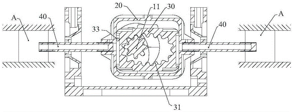
[0062] Picture 11 with Picture 12 Shown is a two-stroke opposed-piston engine. The opposed-piston engine includes at least a pair of linear reciprocating units arranged on the planes on both sides of the axis of the main shaft 10, and the linear reciprocating body A is arranged in the cylinder 50 Piston 51. The axial connecting rod 40 is an inner axial connecting rod 40a whose outer end is fixedly connected to the piston 51, and the push-pull frame 20 is a first push-pull frame 20a. The inner end of the inner shaft connecting rod 40a is fixedly connected to one side of the first push-pull frame 20a, an exhaust valve 58 is provided on the outer end cover 52b of the cylinder 50, and a timing system is provided between the main shaft 10 and the exhaust valve 58 The timing system cooperates with the air intake port 55 controlled by the piston stroke to perform gas distribution in a two-stroke working mode.

[0063] Reference Picture 12 The timing system includes an outer frame-sh...


PUM


Abstract

The invention discloses a shaft type connecting rod transmission system and an opposed piston engine; and a traditional reciprocating linear motion is converted to a rotating motion in the same direction, so that the reliability of the transmission system is effectively improved, the transmission system is simplified to become more compact, and effective utilization of a space between the back surface of a piston of an internal combustion engine and a cylinder becomes possible. The shaft type connecting rod transmission system comprises a main shaft and at least one linear reciprocating motion unit, wherein the linear reciprocating motion unit comprises at least one linear reciprocating motion body. The linear reciprocating motion bodies are fixedly connected with one ends of corresponding shaft type connecting rods; the other ends of the shaft type connecting rods are fixedly connected with one sides of corresponding push-pull frames; and the axles of the shaft type connecting rods and the main shaft are perpendicular to each other. Slip blocks are arranged in the push-pull frames; two transverse outer side walls of the slip blocks and two transverse inner side walls of the push-pull frames are formed to vertical slide fit; inner rings of the slip blocks have inner teeth with elliptic indexing circles; and the inner teeth are circularly engaged with gears correspondingly arranged on the main shaft. Reversing mechanisms are arranged between the main shaft and the slip blocks.

Description

Technical field [0001] The invention relates to a shaft type connecting rod transmission system that converts linear reciprocating motion into rotation motion, and an opposed piston engine adopting the shaft type connecting rod transmission system. Background technique [0002] At present, the most popular piston engine is the crankshaft connecting rod piston engine. The crankshaft connecting rod mechanism converts the linear reciprocating motion of the piston into the crankshaft rotary motion, but the crank connecting rod mechanism reduces the efficiency of the piston engine and the fuel utilization efficiency Only about 30%. [0003] In order to improve the efficiency of the piston engine, the structure of the piston engine and its transmission system have been continuously improved. [0004] For example, in the invention patent application specification with the publication number CN102003282, an internal rack-and-pinion linkage mechanism for the external gear shaft of an engine ...

Claims


Application Information

Patent Timeline
IPC IPC(8): F02B75/32F02B75/24F16H37/12
Inventor 郑安庆
Owner 郑安庆
Why Eureka
Try Eureka