Geogrid strain measuring device and measuring method in model test
A model test, geogrid technology, applied in the direction of measuring device, mechanical measuring device, using mechanical device, etc., can solve the problem of deepening the understanding of the deformation characteristics and deformation laws of geogrids, and easy to damage and strain during sample preparation and testing. It can solve the problems such as distortion of the measurement results of the wafer, and achieve the effect of expanding the layout space, simplifying the strain measurement process and simple structure.
- Summary
- Abstract
- Description
- Claims
- Application Information
AI Technical Summary
Problems solved by technology
Method used
Image
Examples
Embodiment 1
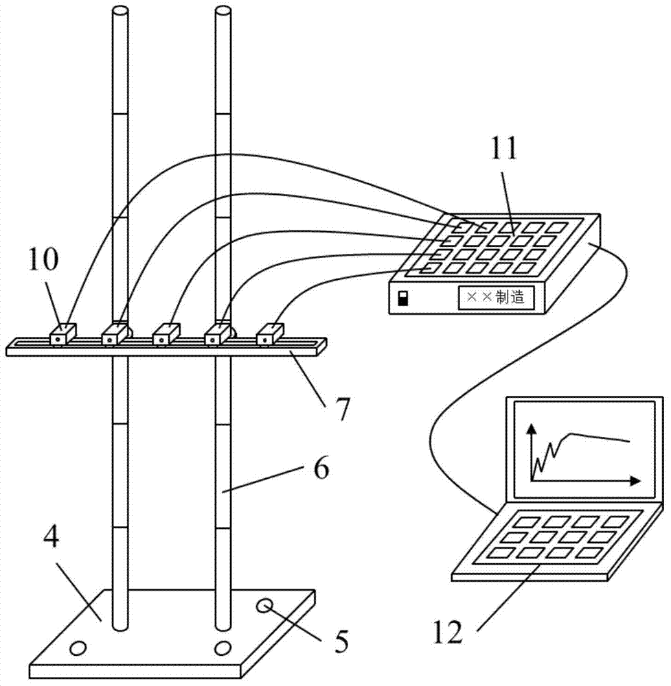
[0038] A geogrid strain measuring device in a model test, such as Figure 1 to Figure 8 As shown, it includes a stainless steel string 1, a base 4, a bracket (composed of a column 6, a chute 7, a sliding fastener 8 and a set screw 9), a wire distribution frame (composed of a set screw 9, a pulley 13, a crank arm 14 and The cross bar 15 is composed together), the displacement meter 10 and the measurement system (composed of the static strain acquisition instrument 11 and the portable laptop computer 12). The bracket is fixed on the base 4; the displacement gauge 10 is movably set on the bracket and connected to the measurement system; one or more measuring points 3 are set on the geogrid to be tested, and each measuring point 3 passes through the stainless steel string 1 Connected to displacement meter 10.
[0039] see figure 1 as well as figure 2, the bracket used in the present invention includes a column 6, a positioning screw 9, a sliding fastener 8 and a chute 7; the c...
Embodiment 2
[0048] Apply the geogrid strain measurement device of Example 1 to the grid strain measurement in the three-way geogrid 23 indoor pull-out test, the specific steps are:
[0049] 1) Connect the stainless steel string 1 to the measuring point 3 on the three-way geogrid 23, one measuring point 3 corresponds to one stainless steel string 1, and a total of twelve stainless steel strings 1 are used;
[0050] 2) Place the three-way geogrid 23 connected to the stainless steel string 1 in the drawing instrument, and the other end of the stainless steel string 1 is connected to the displacement meter 10 outside the drawing instrument; combine the three rows of chute 7 with the branching frame Use, fix four displacement gauges 10 on every row of chute 7, totally twelve;
[0051] 3) Adjust the position of the base 4, so that the stainless steel string 1 is in a tensioned state; adjust the height of the chute 7 and the wire distribution frame, so that the stainless steel string 1 before an...
Embodiment 3
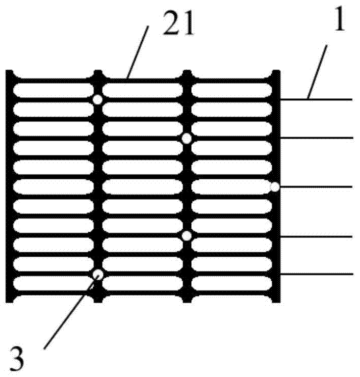
[0056] The geogrid strain measurement device of embodiment 1 is applied to the grid strain measurement in the model test of the unidirectional geogrid 21 reinforced expansive soil slope stability research under the rainfall condition. The strain of the three-layer unidirectional geogrid 21 with different heights and a vertical interval of 150 mm, but there are fewer measuring points 3 on each layer of the grid, and the test time and reading interval are longer, so the displacement meter 10 adopts a dial indicator , manual reading, the chute 7 has three rows, no wire distribution frame and measuring device are needed, the specific steps are:
[0057] 1) Connect the stainless steel string 1 to the measuring point 3 on the one-way geogrid 21, one measuring point 3 corresponds to one stainless steel string 1, there are five measuring points 3 on each layer of the one-way geogrid 21, a total of ten Five stainless steel strings 1;
[0058] 2) Place the one-way geogrid 21 connected ...
PUM
 Abstract
Description
Claims
Application Information
 - R&D
- Intellectual Property
- Life Sciences
- Materials
- Tech Scout
- Unparalleled Data Quality
- Higher Quality Content
- 60% Fewer Hallucinations
Browse by: Latest US Patents, China's latest patents, Technical Efficacy Thesaurus, Application Domain, Technology Topic, Popular Technical Reports.
© 2025 PatSnap. All rights reserved.Legal|Privacy policy|Modern Slavery Act Transparency Statement|Sitemap|About US| Contact US: help@patsnap.com


