Exhaust gas disposal device

A technology of exhaust treatment device and mixing device, which is applied to exhaust devices, mufflers, engine components, etc., can solve the problems of ammonia leakage, engine power performance decline, blockage of exhaust pipes, etc., to increase evaporation area, The effect of improving evaporation rate and improving uniformity

Active Publication Date: 2015-12-09
TENNECO SUZHOU EMISSION SYST
View PDF6 Cites 12 Cited by
  • Summary
  • Abstract
  • Description
  • Claims
  • Application Information

AI Technical Summary

Problems solved by technology

If the distribution of ammonia is not uniform, it will lead to excessive ammonia in some areas, which will easily cause ammonia leakage, and the conversion efficiency of nitrogen oxides (NOx) will be too low in other ammonia-lean areas.
Uneven distribution of ammonia over a long period of time can lead to uneven catalyst aging, which affects the overall performance of the catalyst
In addition, the uneven distribution of urea droplets will cause the temperature of the local pipe wall or mixing structure to be too low, forming crystallization, which will block the exhaust pipe in serious cases and cause the engine power performance to decline

Method used


Image

  • Exhaust gas disposal device
  • Exhaust gas disposal device
  • Exhaust gas disposal device

Examples


Embodiment Construction

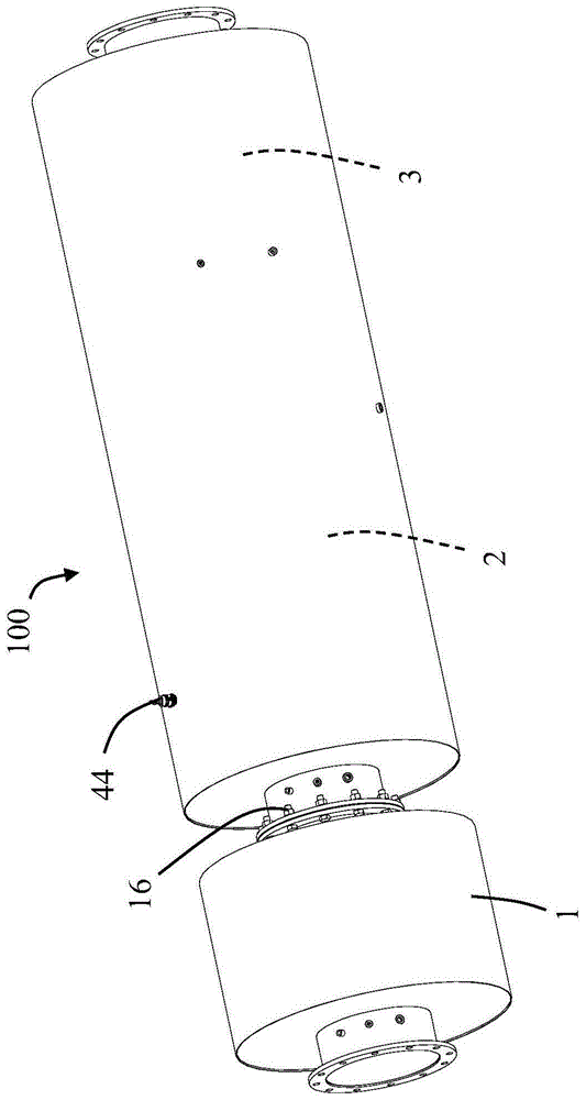
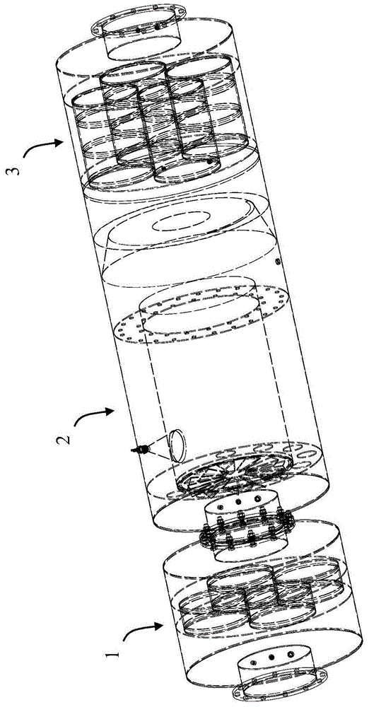
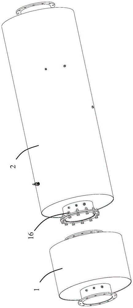
[0029] Please refer to Figure 1 to Figure 7 As shown, the present invention discloses an exhaust treatment device 100 for treating the exhaust of an engine (especially a high-power engine). Overall, the exhaust gas treatment device 100 includes a first reactor 1 , a mixing structure 2 and a second reactor 3 . In the illustrated embodiment of the invention, the first reactor 1 is located upstream of the second reactor 3 in the flow direction of the exhaust gas. Functionally, the first reactor 1 is an oxidation catalyst (DOC). The second reactor 3 includes a tail gas treatment module 31 , and the tail gas treatment module 31 is a selective catalytic reduction module (SCR) in the illustrated embodiment of the present invention. Of course, those skilled in the art can understand that the exhaust treatment device 100 of the present invention may also include a third reactor, such as an ammonia slip catalyst module (ASC). The various reactors mentioned above can be designed as o...


PUM


Abstract

An exhaust gas disposal device comprises a shell, partition plates, a mixing cavity, a distributing cavity and a tail gas disposal module. The exhaust gas disposal device comprises a mixing device erected in the mixing cavity, and thus the mixing cavity is divided into a first cavity, a second cavity and a third cavity. The mixing device comprises a mixing pipe and a spinning disk installed on the mixing pipe, wherein the spinning disk comprises a plurality of fins which stretch into the first cavity in a protruding manner and are arranged in the circumferential direction. The exhaust gas disposal device further comprises a jet limiting cylinder fixed to the mixing pipe, and the jet limiting cylinder is used for enabling a urea nozzle to lead an atomized urea solution into the mixing pipe. Urea is evenly distributed on the pipe wall of the mixing pipe through centrifugal force generated by rotational flow, the urea evaporation area is increased, and the evaporation rate is increased. In addition, the distributing cavity is used for improving the distribution uniformity of urea liquid drips entering the distributing cavity from the mixing cavity, and thus the risk of urea crystallization is reduced.

Description

technical field [0001] The invention relates to an exhaust treatment device, which belongs to the technical field of engine exhaust post-treatment. Background technique [0002] Studies have shown that the uniformity of ammonia distribution in the pipeline of exhaust aftertreatment systems (such as selective catalytic reduction systems, SCR systems) has an important impact on the overall performance and durability of the system. If the distribution of ammonia is not uniform, it will lead to excessive ammonia in local areas, which will easily cause ammonia leakage, and the conversion efficiency of nitrogen oxides (NOx) will be too low in other ammonia-lean areas. The uneven distribution of ammonia over a long period of time can lead to uneven catalyst aging, which affects the overall performance of the catalyst. In addition, the uneven distribution of urea droplets will cause the temperature of the local pipe wall or mixing structure to be too low, forming crystallization, w...

Claims


Application Information

Patent Timeline
Patent Type & Authority Applications(China)
IPC IPC(8): F01N3/28
Inventor 曹刚李硕王平
Owner TENNECO SUZHOU EMISSION SYST
Why Eureka
Try Eureka