Electro-hydraulic-servo-driven valve controlling device

A technology of valve controller and electro-hydraulic servo, applied to servo motors, valve details, valve devices, etc., can solve problems such as energy waste, valve control failure, safety hazards, etc., to improve stability and reliability, and reduce failures The effect of probability and reliability guarantee

Inactive Publication Date: 2015-12-09
JIANGSU UNIV
View PDF8 Cites 5 Cited by
  • Summary
  • Abstract
  • Description
  • Claims
  • Application Information

AI Technical Summary

Problems solved by technology

However, the disadvantage of the traditional valve controller system is that the servo valve is used as the control element of the hydraulic cylinder. The servo valve is very sensitive to the cleanliness of the hydraulic oil. After a period of use, the hydraulic oil pollution will consume the hydraulic components in the servo valve. The use of valves in pipelines is a very dangerous situation, and there is a huge potential safety hazard; and the servo valve is always working during the entire control process, which uses more energy and causes energy waste; in addition, the current Some valve controllers only have a single servo valve to control the hydraulic cylinder. Once the servo valve fails, it will inevitably cause the valve control to fail.

Method used


Image

  • Electro-hydraulic-servo-driven valve controlling device
  • Electro-hydraulic-servo-driven valve controlling device
  • Electro-hydraulic-servo-driven valve controlling device

Examples


Embodiment Construction

[0023] The present invention will be further described below in conjunction with the accompanying drawings and specific embodiments, but the protection scope of the present invention is not limited thereto.

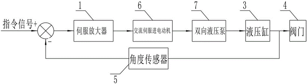
[0024] Such as figure 2 As shown, the control principle of the electro-hydraulic servo valve controller described in the present invention is: the control signal of the host computer inputs the instruction for driving the valve into the servo amplifier 1, and the angle sensor 5 measures the angular displacement feedback of the rack-and-pinion hydraulic cylinder 3 The signal is sent to the servo amplifier 1, and the servo amplifier 1 amplifies and compares the two signals and outputs them to the AC servo motor 6, and the AC servo motor 6 drives the two-way gear quantitative hydraulic pump 7 to run after receiving the electric control signal of the servo amplifier 1, thereby The movement of the hydraulic cylinder 3 is driven by the hydraulic circuit, and the valve 4 realiz...


PUM


Abstract

The invention provides an electro-hydraulic-servo-driven valve controlling device. The valve controlling device comprises a pinion-and-rack hydraulic cylinder, two sets of electro-hydraulic servo power sources and an electronic control part. The electronic control part comprises a controller, a displayer, a control switch and an angle transducer, wherein the displayer, the control switch and the angle transducer are connected with the controller. The angle transducer is fixed to the upper portion of the pinion-and-rack hydraulic cylinder. A rotating shaft of the pinion-and-rack hydraulic cylinder is connected with a rotating shaft of the angle transducer. The rotating shaft of the pinion-and-rack hydraulic cylinder is connected with a rotating shaft of a valve. Each set of electro-hydraulic servo power source comprises a bidirectional gear quantitative hydraulic pump, an alternating-current servo motor, a pressure oil tank and a double-hydraulic control one-way valve which are connected with the controller. Output shafts of the alternating-current servo motors and input shafts of the hydraulic pumps are connected. The pressure oil tanks are communicated with low-pressure oil suction openings of the hydraulic pumps through the one-way valves. Two outlets of the bidirectional gear quantitative hydraulic pumps of the two sets of electro-hydraulic servo power sources are communicated with the hydraulic cylinder through the double-hydraulic control one-way valves. The valve controlling device has the beneficial effects of being good in reliability, capable of saving energy and efficient.

Description

technical field [0001] The invention relates to a valve controller, in particular to an electro-hydraulic servo-driven valve controller. Background technique [0002] The valve drive controller is a kind of controller that can quickly and accurately control and monitor the working position of the valve, so it is widely used in important fields such as industrial pipelines, ship ballast water, and fire-fighting water systems. The remote control of the valve controller can control the opening, closing and opening of the valve in the pipeline, so as to achieve the purpose of controlling the oil flow rate and load in the pipeline and protecting the rapid closure of pipeline circulation to achieve safety. [0003] The structure diagram of the traditional valve controller system is as follows: figure 1 shown. The upper computer monitors the position of the valve and sends out a command signal. The command signal works together through the servo amplifier, servo valve, hydraulic ...

Claims


Application Information

Patent Timeline
Patent Type & Authority Applications(China)
IPC IPC(8): F16K31/12F15B11/08
CPCF16K31/12F15B11/08
Inventor 顾寄南沈雨春陈功
Owner JIANGSU UNIV
Why Eureka
Try Eureka