
Boiler device

A boiler device and boiler shell technology, applied in steam boilers, combustion methods, fluid heaters, etc., can solve the problems of inability to clearly observe the combustion situation of the furnace body, small contact area between briquettes or briquettes and air, and low boiler heat transfer efficiency and other problems, to achieve the effect of simple structure, reducing heat loss and reasonable design

Inactive Publication Date: 2015-12-09
杨晓方
View PDF7 Cites 2 Cited by
  • Summary
  • Abstract
  • Description
  • Claims
  • Application Information

AI Technical Summary

Problems solved by technology

[0004] Boilers are indispensable equipment in power plants. Existing boilers generally burn briquettes or briquettes directly. In this way, the contact area between briquettes or briquettes and air is small during the combustion process, which is insufficient in the combustion process. At the same time, the heat transfer efficiency of the boiler Low, resulting in a large energy loss of the boiler, at the same time can not clearly observe the internal combustion of the furnace

Method used


Image

  • Boiler device

Examples


Embodiment Construction

[0014] In order to make the object, technical solution and advantages of the present invention clearer, the present invention will be further described in detail below in conjunction with the accompanying drawings and embodiments. It should be understood that the specific embodiments described here are only used to explain the present invention, not to limit the present invention.

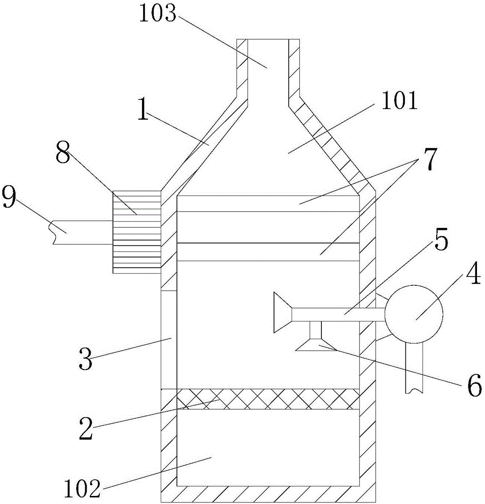
[0015] see figure 1 , figure 1 It is a structural schematic diagram of the present invention.

[0016] A boiler device, comprising a boiler shell 1, a combustion partition 2 is arranged inside the boiler shell 1, and the combustion partition 2 divides the boiler shell 1 into a combustion chamber 101 and an ash collection chamber 102, and the boiler shell The upper end of the body 1 is provided with a dust discharge hole 103, and the side wall of the boiler shell 1 is provided with an observation window 3 and a conveying pump 4, wherein the conveying pump 4 and the boiler shell 1 are detachably co...


PUM


Abstract

The invention relates to a boiler device. The boiler device comprises a boiler shell. A burning partition plate is arranged inside the boiler shell, and the boiler shell is divided by the burning partition plate into a burning cavity and an ash collecting cavity. A dust discharging hole is formed in the upper end of the boiler shell, a viewing window and a delivering pump are arranged on the side wall of the boiler shell, and the delivering pump is connected with one end of a delivering pipe. Two powder spraying covers are arranged on the delivering pipe. A plurality of heat collecting pipes are arranged on the upper side of the interior of the boiler shell and connected with a heat collector, and one end of the heat collector is connected with a heat transferring pipe. According to the boiler device, under the effect of the delivering pump, coal powder is loaded through high pressure and then sprayed out through the powder spraying covers, so that the contact area of the coal powder and air can be increased, burning is more sufficient, and the burning using ratio is increased; meanwhile, heat can be timely collected and transferred under the effects of the heat collecting pipes and the heat collector, the heat transmitting efficiency is improved, and heat losses are reduced.

Description

technical field [0001] The invention relates to the technical field of power plants, in particular to a boiler device. Background technique [0002] A power plant refers to a power plant that converts some form of raw energy into electrical energy for fixed facilities or transportation, such as thermal power, hydraulic power, steam, diesel or nuclear power plants, etc. [0003] The boiler is a kind of energy conversion equipment. The energy input to the boiler includes chemical energy and electric energy in the fuel, and the boiler outputs steam, high-temperature water or organic heat carrier with a certain amount of heat energy. The original meaning of the pot refers to the water container heated on the fire, and the furnace refers to the place where fuel is burned. The boiler includes two parts: the pot and the furnace. The hot water or steam generated in the boiler can directly provide the required heat energy for industrial production and people's life, and can also be ...

Claims


Application Information

Patent Timeline
Patent Type & Authority Applications(China)
IPC IPC(8): F22B31/00F24H1/22F23K3/00
Inventor 杨晓方
Owner 杨晓方
Learn More