Steel tape automatic verification system
A steel tape measure and automatic technology, applied in the direction of a bendable ruler, etc., can solve the problems of a large amount of labor, a cumbersome calibration error process, etc., and achieve the effects of low cost, reduced labor intensity, and simple overall structure.
- Summary
- Abstract
- Description
- Claims
- Application Information
AI Technical Summary
Problems solved by technology
Method used
Image
Examples
Embodiment 1
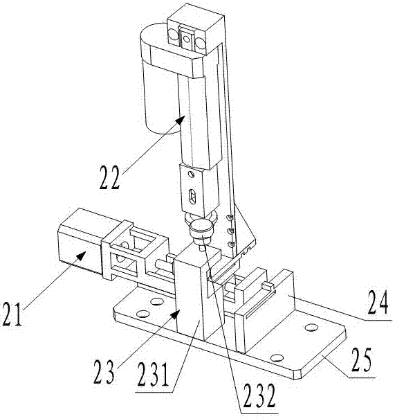
[0034] Such as figure 1 , figure 2 and Figure 5 As shown, the steel tape automatic verification system includes a horizontal horizontal support 1, a zero alignment device 2, a tension loading and unloading device 3 and a camera 11, wherein the zero alignment device 2, a tension loading and unloading device 3 and a camera 11 They are all arranged on the horizontal horizontal support 1, and the zero alignment device 2 and the tension loading and unloading device 3 are respectively close to the left and right ends of the horizontal horizontal support 1. The zero alignment device 2 of the present embodiment includes a precision displacement workbench 21, a checked ruler pressing mechanism 22, a standard ruler pressing mechanism 23 and a zero alignment device base 25, wherein the precision displacement workbench 21, the checked ruler pressing mechanism The tightening mechanism 22 and the standard ruler pressing mechanism 23 are all fixed on the zero alignment device base 25, an...
Embodiment 2
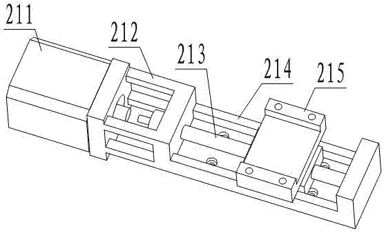
[0037] Such as figure 2 , image 3 and Figure 4 As shown, the present embodiment makes the following further limitations on the basis of Embodiment 1: the precision displacement table 21 of the present embodiment includes a first horizontal slider 215 and a level for driving the first horizontal slider 215 to horizontally and horizontally displace. Drive mechanism. The checked ruler pressing mechanism 22 includes a support frame 221, a linear actuator 222, a connecting rod 223, a pressure head 224 and a checked workbench 225, and the support frame 221 and the checked workbench 225 are fixed on the first horizontal slider 215 , the linear actuator 222 is fixed on the support frame 221, and the pressure head 224 is arranged directly above the tested workbench 225 and is connected to the linear actuator 222 through the connecting rod 223, and is driven by the linear actuator 222 to move up and down. In this embodiment The horizontal height of the upper end surface of the pla...
Embodiment 3
[0040] This embodiment makes the following further limitations on the basis of Embodiment 2: the precision displacement table 21 of this embodiment also includes a flange 212 and a precision displacement table support seat 214, and the precision table 21 of this embodiment is specifically passed The support seat 214 of the precision displacement workbench is fixed on the base 25 of the zero alignment device. The horizontal drive mechanism includes a stepper motor 211 and a precision transmission screw 213. The stepper motor 211 is connected to the support seat 214 of the precision displacement workbench through a flange 212. At the left end, the left end of the precision transmission screw rod 213 is connected with the stepper motor 211 . The first horizontal slider 215 of this embodiment is installed on the precision transmission screw 213 and driven by the stepping motor 211 to move horizontally. In the actual implementation of this embodiment, the first horizontal slider 21...
PUM
 Abstract
Description
Claims
Application Information
 - R&D
- Intellectual Property
- Life Sciences
- Materials
- Tech Scout
- Unparalleled Data Quality
- Higher Quality Content
- 60% Fewer Hallucinations
Browse by: Latest US Patents, China's latest patents, Technical Efficacy Thesaurus, Application Domain, Technology Topic, Popular Technical Reports.
© 2025 PatSnap. All rights reserved.Legal|Privacy policy|Modern Slavery Act Transparency Statement|Sitemap|About US| Contact US: help@patsnap.com


