ct polarity testing device

A technology of polarity testing and anode, which is applied in the direction of measuring devices, measuring electricity, and measuring electrical variables, etc., can solve the problems of small current, high precision requirements, and high cost, and achieve low energy consumption, low power consumption, and convenient operation Effect

Active Publication Date: 2017-12-12
STATE GRID CORP OF CHINA +2
View PDF9 Cites 0 Cited by
  • Summary
  • Abstract
  • Description
  • Claims
  • Application Information

AI Technical Summary

Problems solved by technology

If the current transformer is relatively large, the secondary induced current will be very small, which requires high accuracy of the ammeter on the secondary side, and the cost will be high, and this method cannot be used for currents with relatively large transformation ratios. The transformer responds very well

Method used


Image

  • ct polarity testing device
  • ct polarity testing device

Examples


Embodiment Construction

[0015] The present invention will be further described in detail below with reference to the accompanying drawings and specific embodiments.

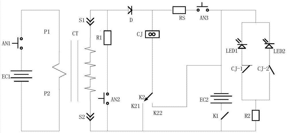
[0016] figure 1 The circuit structure of the embodiment of the present invention and the line connection structure between it and the current transformer CT are shown.

[0017] like figure 1 As shown, the embodiment of the present invention includes a first resistor R1, a second resistor R2, a third resistor RS, a diode D, a relay CJ, a first switch AN1, a second switch AN2, a third switch AN3, a single-pole double-throw switch K2, Switch K1, first DC power source EC1, second DC power source EC2, first light emitting diode LED1, second light emitting diode LED2.

[0018] Specifically, the first end of the first resistor R1 is connected to the first end of the second switch AN2, the second end of the first resistor R1 is connected to the anode of the diode D, and the second end of the second switch AN2 is connected to the single pole ...


PUM


Abstract

A CT polarity testing device, which includes: a first resistor (R1), a second resistor (R2), a third resistor (RS), a diode (D), a relay (CJ), a first switch (AN1), a second Second switch (AN2), third switch (AN3), single pole double throw switch (K2), switch (K1), first DC power supply (EC1), second DC power supply (EC2), first light emitting diode (LED1) , the second light emitting diode (LED2). The invention fully meets the actual needs of the relay protection work site, has the characteristics of sensitive testing, convenient operation, portability, reliability and practicality, etc., can greatly improve the working efficiency of the site, and the test light indication is intuitive and specific, and the power consumption of electronic components is small , low cost, low energy consumption, and can be used for long-term testing.

Description

technical field [0001] The invention relates to the technical field of power equipment maintenance and power instrument testing, in particular to a CT polarity test device. Background technique [0002] Current transformer (CT for short) is based on the principle of electromagnetic induction, which converts a large current on the primary side into a small current on the secondary side for use. It is usually composed of a closed iron core and windings. Its primary side winding is connected in series with the circuit of the current to be measured, and the secondary side winding is connected in series with the measuring instrument and the protection circuit. When the current transformer is working, the secondary side loop is always closed, the working state of the current transformer is close to short circuit, and the secondary side cannot be opened. [0003] In the secondary production work of the power system, the current transformer replacement and overhaul projects are oft...

Claims


Application Information

Patent Timeline
Patent Type & Authority Patents(China)
IPC IPC(8): G01R31/06
Inventor 崔良张立辉刘守瑞李晓影乔辉王江涛
Owner STATE GRID CORP OF CHINA
Why Eureka
Try Eureka