Fiber Optic Connector Assemblies

A fiber optic connector and component technology, which is applied in the field of fiber optic connector components, can solve the problems of high sensitivity of optical signals to dust and dirt, unfavorable optical signal transmission, and easy entry of dust, so as to reduce production difficulty, reduce transmission impact, reduce The effect of sensitivity

Active Publication Date: 2018-04-24
CHINA AVIATION OPTICAL-ELECTRICAL TECH CO LTD
View PDF4 Cites 0 Cited by
  • Summary
  • Abstract
  • Description
  • Claims
  • Application Information

AI Technical Summary

Problems solved by technology

The existing problem of this kind of optical fiber connector is: because the outer diameter of the optical fiber core is at the μm level, coupled with the characteristics of the light itself, it is extremely sensitive to the quality of the end face of the joint. In actual use, the male fiber and the female fiber The plugging position of the fiber optic ferrule is easy to enter dust. Once the end face of the fiber optic ferrule is covered with dust, the optical path radius formed by the fiber optic female head is relatively small, and the optical density per unit area is relatively large. The sensitivity of the optical signal to dust and dirt is very high. The transmission of optical signals is greatly disadvantageous

Method used


Image

  • Fiber Optic Connector Assemblies
  • Fiber Optic Connector Assemblies
  • Fiber Optic Connector Assemblies

Examples


Embodiment Construction

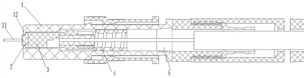
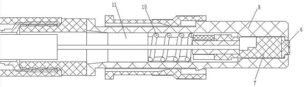
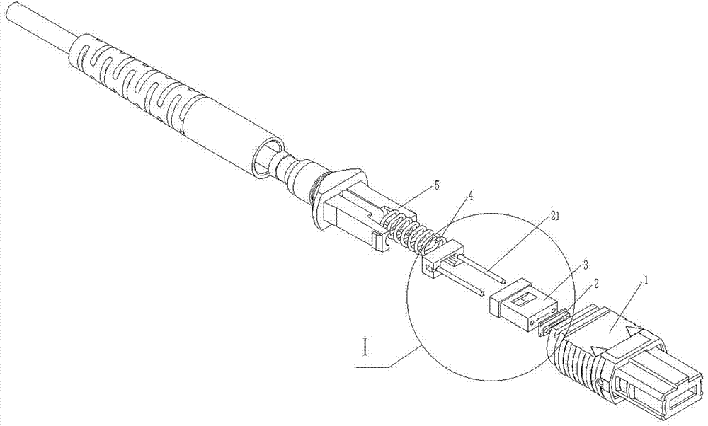
[0024] Examples of fiber optic connector assemblies are Figure 1~8 As shown: it includes the male fiber optic connector and the female fiber optic connector. The rear end of the body is provided with a male rear sleeve 5, and the male optical fiber core is equipped with a male optical fiber core guided and moved along the front and rear directions in the male housing. The rear side of the male optical fiber core is provided with a Active male spring 4. The male fiber optic ferrule includes a male lens seat 2 and a male ferrule mounting seat 3 which are separately arranged at the front and rear. The male optical core channel 18 is arranged on the male ferrule mounting seat, and the male optical core channels form an array multi-core The optical channel, the male optical core channel 18 and the male ferrule mounting seat 3 constitute the MT ferrule, and the male lens seat 2 is provided with a male lens 19 respectively located at the front side of the corresponding male optical...


PUM


Abstract

The invention relates to an optical fiber connector assembly, and the assembly comprises an optical fiber male head and an optical fiber female head. An optical fiber insertion core of the optical fiber male head comprises a male head lens seat and a male head insertion core installation seat provided with a male head optical core channel, wherein the male head lens seat and the male head insertion core installation seat are arranged in a split manner. The male head lens seat is provided with a male head lens which is located at a front side of the corresponding male head optical core channel, and a front end part of the male head optical core channel is located at a focus position of the male lens. A female head optical fiber insertion core comprises a female head lens seat and a female head insertion core installation seat provided with a female head optical core channel. The female head lens seat is provided with a female head lens which is located at the front side of the corresponding female head optical core channel, and the front end part of the female head optical core channel is located at the focus position of the female head lens. One of the male head lens and the female head lens serves as a beam-expanding lens which is used for the beam expansion of a corresponding optical signal, and the other one of the male head lens and the female head lens serves as a beam bunching lens which is used for the beam bunching of the optical signal after beam expansion. The assembly provided by the invention can reduce the optical density of a unit area.

Description

technical field [0001] The invention relates to an optical fiber connector assembly for optical signal transmission. Background technique [0002] As a relatively common optical fiber connector, MPO optical fiber connector has a wide range of applications. Existing MPO optical fiber connectors, such as "a high-density MPO multi-core optical fiber connector" disclosed in Chinese patent CN202583527U, include outer frames and The bracket is arranged at the rear end of the outer frame. The outer frame is equivalent to the shell. The outer frame is guided and moved along the front and rear direction and is equipped with a ferrule. The front face of the ferrule constitutes an optical positioning surface. A spring is provided between the cores to apply a forward force to the ferrule, and a limiting structure is provided on the outer frame to limit the limit of the forward movement of the ferrule. The above-mentioned fiber optic connector is a fiber optic male head, and the fiber o...

Claims


Application Information

Patent Timeline
Patent Type & Authority Patents(China)
IPC IPC(8): G02B6/26G02B6/36G02B6/38
CPCG02B6/264G02B6/3616G02B6/3624G02B6/38
Inventor 胡治国刘涛陈娜娜
Owner CHINA AVIATION OPTICAL-ELECTRICAL TECH CO LTD
Why Eureka
Try Eureka