Annular channel liquid metal magnetohydrodynamic generator

A magnetic fluid generator and magnetic fluid power generation technology, which is applied in the direction of electrical components, electromechanical devices, etc., can solve the problems of increasing contact resistance and wiring voltage loss, limitation, increasing the size, cost and cost of the power generation device, etc. Internal resistance and output voltage, the effect of reducing the cost of the device

Inactive Publication Date: 2015-12-09
INST OF ELECTRICAL ENG CHINESE ACAD OF SCI
View PDF9 Cites 7 Cited by
  • Summary
  • Abstract
  • Description
  • Claims
  • Application Information

AI Technical Summary

Problems solved by technology

However, the series connection of multiple power generation channels not only increases the size, cost and cost of the power generation device, but also increases the contact resistance and the voltage loss of the wiring, and the ability to increase the output voltage is very limited.
In addition, the synchronization of the output of multiple power generation units is also a problem

Method used


Image

  • Annular channel liquid metal magnetohydrodynamic generator
  • Annular channel liquid metal magnetohydrodynamic generator
  • Annular channel liquid metal magnetohydrodynamic generator

Examples


Embodiment Construction

[0028] The present invention will be further described below in conjunction with the accompanying drawings and specific embodiments.

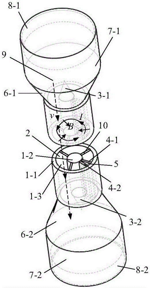
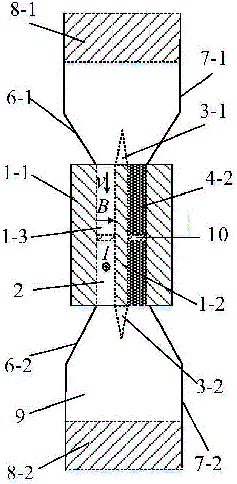
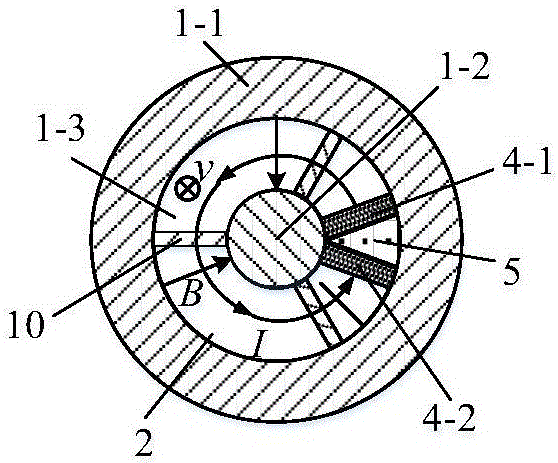
[0029] figure 1 It is a three-dimensional schematic diagram of an annular channel liquid metal magnetic fluid generator according to an embodiment of the present invention, and the center of the liquid metal magnetic fluid generator is cut along a radial section. Figure 2a It is the front view of the annular channel liquid metal magnetic fluid generator of the embodiment of the present invention, Figure 2b It is a radial cross-sectional view of an annular channel liquid metal magnetic fluid generator according to an embodiment of the present invention. Such as figure 1 , Figure 2a with Figure 2b As shown, the annular magnetic fluid power generation channel 2 passes through the annular magnetic hole 1-3 of the magnet; the first magnetic fluid channel transition section 6-1 and the second magnetic fluid channel transition section 6-2 are ...


PUM


Abstract

The invention provides an annular channel liquid metal magnetohydrodynamic generator of which an annular magnetohydrodynamic generation cahnnel (2) penetrates through a magnet annular magnetic hole (1-3); and magnetohydrodynamic channel transition segments (6-1, 6-2) are symmetrically connected at the two ends of the annular magnetohydrodynamic generation cahnnel (2). The other end of the first magnetohydrodynamic channel transition segment (6-1) is connected with a first piston cylinder (7-1). The other end of the second magnetohydrodynamic channel transition segment (6-2) is connected with a second piston cylinder (7-2). A first piston (8-1) is coaxially arranged in the first piston cylinder (7-1). A second piston (8-2) is coaxially arranged in the second piston cylinder (7-2) A sealed communicating space is formed by the pistons, the piston cylinders, the magnetohydrodynamic channel transition segments and the annular magnetohydrodynamic generation channel (2), and the communicating space is fully filled with liquid metal (9). Liquid metal (9) flows along an axial direction in the annular magnetohydrodynamic generation channel (2) so that radial magnetic lines of force are cut and tangential induced current is generated.

Description

technical field [0001] The invention relates to a liquid metal magnetofluid generator, in particular to a liquid metal magnetofluid generator adopting a circular power generation channel. Background technique [0002] The new Liquid Metal Magnetic Fluid (Liquid Metal Magnetohydrodynamics, LMMHD) generator uses alternating external forces, such as automobile internal combustion force and wave force, to directly drive liquid metal to reciprocate and linearly move in the power generation channel, cut the magnetic field lines, and generate AC power. Compared with the traditional LMMHD power generation system, such as two-phase flow power generation system and single-phase flow power generation system, the new LMMHD generator adopts direct drive and single-phase liquid metal power generation working fluid, without additional energy and equipment to maintain a good working fluid Conductivity, simple structure, high power density, and high efficiency, so it has broad application pr...

Claims


Application Information

Patent Timeline
Patent Type & Authority Applications(China)
IPC IPC(8): H02K44/08H02K44/14
Inventor 刘艳娇赵凌志彭燕李建张庆贺刘保林沙次文李然夏琦王锋
Owner INST OF ELECTRICAL ENG CHINESE ACAD OF SCI
Why Eureka
Try Eureka