Self-excited BJT type bridgeless Cuk PFC rectification circuit

A rectifier circuit, self-excited technology, applied in electrical components, conversion devices for converting AC power input to DC power output, and output power, etc., can solve problems such as poor self-starting performance, complex MOSFET driving circuit, and low driving efficiency. , to achieve the effect of high driving efficiency, easy self-starting, and simple circuit

Active Publication Date: 2015-12-09
南陵县建设投资有限责任公司
View PDF3 Cites 4 Cited by
  • Summary
  • Abstract
  • Description
  • Claims
  • Application Information

AI Technical Summary

Problems solved by technology

[0005] In order to overcome the deficiencies of the existing MOSFET type bridgeless CukPFC rectifier circuit with complex MOSFET driving circuit, low driving efficiency and poor self-starting performance, t...

Method used


Image

  • Self-excited BJT type bridgeless Cuk PFC rectification circuit
  • Self-excited BJT type bridgeless Cuk PFC rectification circuit
  • Self-excited BJT type bridgeless Cuk PFC rectification circuit

Examples


Embodiment 1

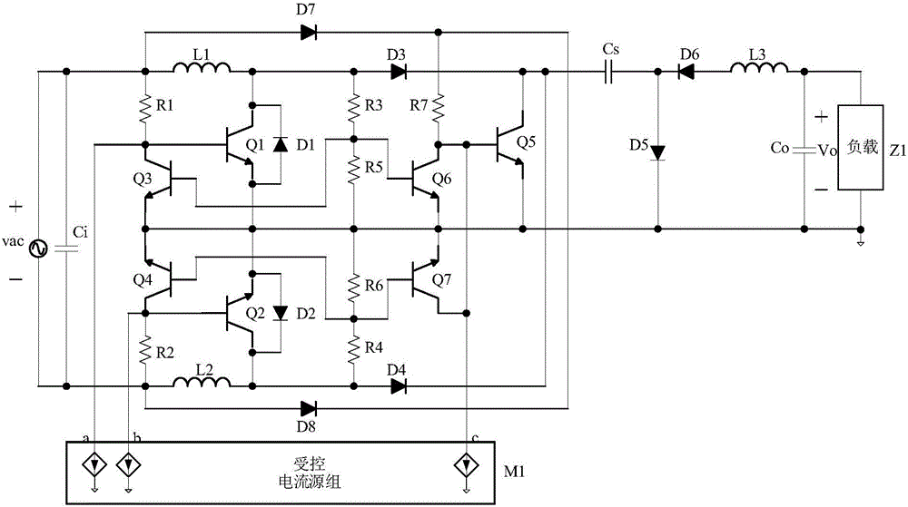
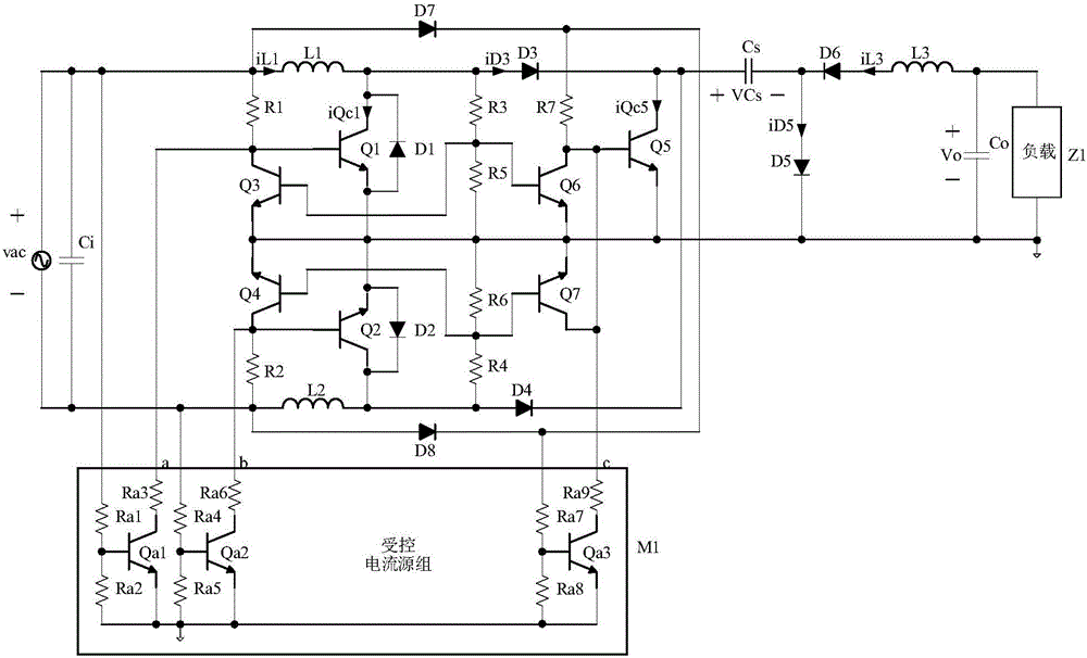
[0024] Embodiment 1: refer to figure 1 , image 3 , Figure 5 and Figure 6 , Embodiment 1 of the present invention has an input voltage feedforward function, which consists of input capacitor Ci, NPN type BJT tube Q1, NPN type BJT tube Q2, NPN type BJT tube Q3, NPN type BJT tube Q4, NPN type BJT tube Q5, NPN Type BJT tube Q6, NPN type BJT tube Q7, diode D1, diode D2, diode D3, diode D4, diode D5, diode D6, diode D7, diode D8, inductor L1, inductor L2, inductor L3, capacitor Cs, output capacitor Co , resistor R1, resistor R2, resistor R3, resistor R4, resistor R5, resistor R6, resistor R7, controlled current source group M1. Among them, the controlled current source M1 is composed of NPN type BJT tube Qa1, NPN type BJT tube Qa2, NPN type BJT tube Qa3, resistor Ra1, resistor Ra2, resistor Ra3, resistor Ra4, resistor Ra5, resistor Ra6, resistor Ra7, resistor Ra8 , Composed of resistor Ra9.

[0025] Such as image 3 As shown, one end of the input capacitor Ci is simultaneou...

Embodiment 2

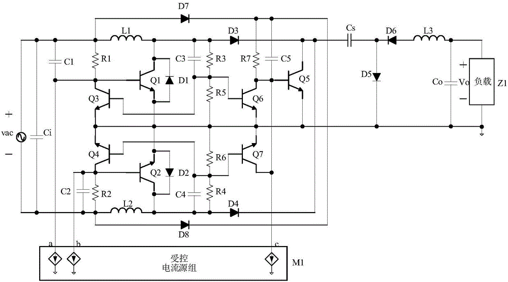
[0037] Embodiment 2: refer to figure 1 , Figure 4 , Figure 7 and Figure 8 , Embodiment 2 of the present invention has output voltage stabilizing function, and it is composed of input capacitor Ci, NPN type BJT tube Q1, NPN type BJT tube Q2, NPN type BJT tube Q3, NPN type BJT tube Q4, NPN type BJT tube Q5, NPN type BJT tube Q6, NPN type BJT tube Q7, diode D1, diode D2, diode D3, diode D4, diode D5, diode D6, diode D7, diode D8, inductor L1, inductor L2, inductor L3, capacitor Cs, output capacitor Co, Composed of resistor R1, resistor R2, resistor R3, resistor R4, resistor R5, resistor R6, resistor R7, and controlled current source group M1. Among them, the controlled current source group M1 is composed of NPN BJT tube Qb1, NPN BJT tube Qb2, NPN BJT tube Qb3, resistor Rb1, resistor Rb2, resistor Rb3, resistor Rb4, resistor Rb5, and capacitor Cb1.

[0038] Such as Figure 4 As shown, one end of the input capacitor Ci is simultaneously connected to the positive end of the ...


PUM


Abstract

Provided is a self-excited BJT type bridgeless Cuk PFC rectification circuit. The rectification circuit comprises an input capacitor Ci, an NPN type BJT transistor Q1, an NPN type BJT transistor Q2, an NPN type BJT transistor Q3, an NPN type BJT transistor Q4, an NPN type BJT transistor Q5, an NPN type BJT transistor Q6, an NPN type BJT transistor Q7, a diode D1, a diode D2, a diode D3, a diode D4, a diode D5, a diode D6, a diode D7, a diode D8, an inductor L1, an inductor L2, an inductor L3, a capacitor Cs, an output capacitor Co, a resistor R1, a resistor R2, a resistor R3, a resistor R4, a resistor R5, a resistor R6, a resistor R7, and a controlled current source group M1. According to the rectification circuit, the structure of a driving circuit is simplified, the driving efficiency is high, and easy self-running performance is obtained.

Description

technical field [0001] The invention relates to a PFC rectifier circuit, which is applied to high-quality electric energy conversion occasions of AC input and DC output, such as: micro energy collection system, new energy power generation system, battery charging system, LED lighting system, etc., especially a bridgeless CukPFC rectifier circuit. Background technique [0002] PFC rectifier circuit is a circuit with power factor correction (PFC) function that can convert AC power into DC power, which can improve the utilization rate of DC load to AC power and reduce the pollution of current harmonics to AC bus or AC power grid. . [0003] The traditional CukPFC rectifier circuit is a PFC rectifier circuit, and its main circuit is generally composed of a bridge rectifier circuit cascaded with a Cuk circuit. In order to reduce the loss of the bridge rectifier circuit, a bridgeless CukPFC rectifier circuit came into being. The bridgeless CukPFC rectifier circuit mainly achiev...

Claims


Application Information

Patent Timeline
IPC IPC(8): H02M7/217
Inventor 陈怡
Owner 南陵县建设投资有限责任公司
Why Eureka
Try Eureka