Plant soil loosening device

A technology for rippers and plants, applied in the fields of application, soil preparation machinery, agricultural machinery and implements, etc., can solve the problems of leaving more unrippled areas, difficult access of motor rippers, and large loosening area, etc. High utilization rate of fertilization, beneficial to irrigation and fertilization, and the effect of improving air permeability

Inactive Publication Date: 2015-12-16
NINGDE NORMAL UNIV
View PDF5 Cites 9 Cited by
  • Summary
  • Abstract
  • Description
  • Claims
  • Application Information

AI Technical Summary

Problems solved by technology

[0003] However, for some scattered plantings, such as the French sycamore, the distance between each other is relatively large, and the above-mentioned plow structure will have three problems: 1. The position of loosening the soil is far away from the tree position, and is far away from the root system of the plant. Loose soil area is large but ventil

Method used


Image

  • Plant soil loosening device
  • Plant soil loosening device
  • Plant soil loosening device

Examples


Embodiment 1

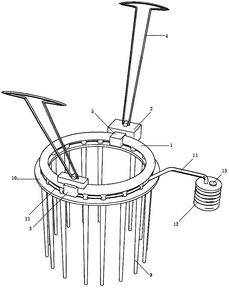
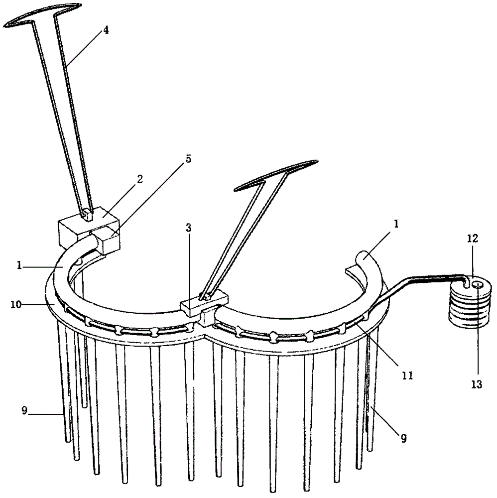
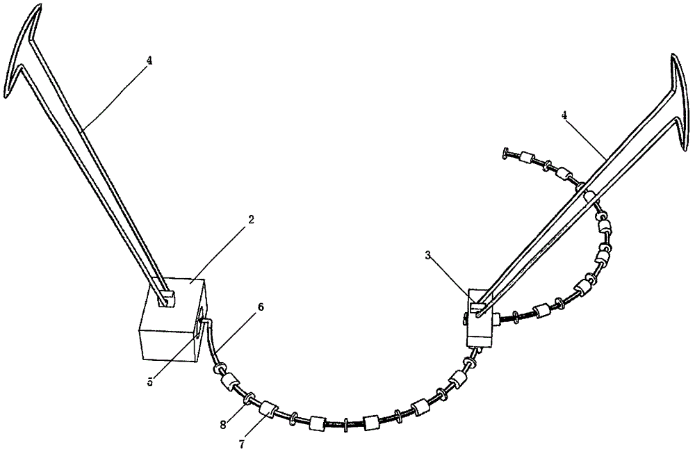
[0016] The plant ripper includes two symmetrically arranged vibrating half-rings 1; one end of the two vibrating half-rings 1 is connected by a rotating shaft and a fixed block 2 is installed on the rotating shaft, and the other end is plugged and fitted with a fixed block B installed on the socket. 3; A fixed block 2 and B fixed block 3 are equipped with a handle 4; A drive motor 5 is installed in the A fixed block 2; the output end of the drive motor 5 is connected to a flexible shaft 6; the flexible shaft 6 passes through two The vibration half-ring 1 circles around in the two vibration half-rings 1; the eccentric rotor 7 is evenly installed on the flexible shaft 6; between the adjacent eccentric rotors 7, the flexible shaft 6 is rotated and connected to the inner wall of the vibration half-ring 1 The supporting wheel 8; the bottom of each vibrating half-ring 1 is evenly equipped with a vertically arranged loosening drill 9; the bottom of each vibrating half-ring 1 is corres...

Embodiment 2

[0020] The difference between this embodiment and embodiment 1 is: on the basis of embodiment 1, each soil ripper 9 inside of the plant ripper is a hollow cavity; the side wall of each ripper 9 is evenly opened with The through hole through which the hollow cavity is connected; the hollow cavity of each soil loosening drill 9 is connected with a hose 11; the end of the hose 11 is connected with a compression capsule 12; the upper part of the compression capsule 12 is equipped with a sealing cover 13.

[0021] This embodiment inherits the operation mode of the embodiment. The soil loosening drill 9 penetrates into the soil when loosening the soil. At this time, the soil looseness is good, which is conducive to irrigation and fertilization, and the utilization rate of irrigation and fertilization is high. At this time, pour water or a mixture of water and fertilizer into the compressed capsule body 12, then press down the compressed capsule body 12, and the liquid enters the soi...

Embodiment 3

[0023] The difference between this embodiment and embodiment 2 is that: on the basis of embodiment 2, the outer wall of each ripper 9 of the plant ripper and the inner wall of the hollow cavity are coated with polytetrafluoroethylene coating.

[0024] This embodiment inherits the operation method of Embodiment 2. The polytetrafluoroethylene coating has strong non-stickiness and corrosion resistance, which can prevent the soil from adhering to the loosening drill 9, and can also prevent the deposition of fertilizing materials from blocking the through hole.


PUM


Abstract

The invention discloses a plant soil loosening device and relates to the technical field of garden cultivation. The plant soil loosening device comprises two vibration semi-rings which are symmetrically arranged; one end of each of the two vibration semi-rings is connected through a rotary shaft and a fixed block A is mounted on the rotary shaft; the other ends of the two vibration semi-rings are matched in an inserting manner and a fixed block B is mounted at the inserting part; a handholding handle is mounted on each of the fixed block A and the fixed block B; the fixed block A is internally provided with a driving motor; the output end of the driving motor is connected with a flexible shaft; the flexible shaft sequentially penetrates through the two vibration semi-rings to surround in the two vibration semi-rings for one circle; eccentric rotors are uniformly mounted on the flexible shaft; between the adjacent eccentric rotors, the flexible shaft is rotationally connected with a supporting wheel fixedly connected with the inner walls of the vibration semi-rings; and soil loosening chisels which are vertically arranged are uniformly mounted at the lower end of each vibration semi-ring. The plant soil loosening device can be used for surrounding a plant for one circle to loosen soil, has high soil loosening efficiency, good soil hardening and crushing effect and high soil ventilation, is convenient to use and is simple to operate.

Description

technical field [0001] The invention relates to the technical field of garden farming. Background technique [0002] At present, the tools used by plants to loosen the soil, whether manual or motorized, are plow structures. The principle is that the blade of the soil loosening tool cuts into the soil and disperses the compacted soil, thereby improving the air permeability of the soil and ensuring the plant root system of aerobic respiration. This method has a fast loosening speed and is suitable for large-scale planting. It is a traditional and effective farming method. [0003] However, for some scattered plantings, such as the French sycamore, the distance between each other is relatively large, and the above-mentioned plow structure will have three problems: 1. The position of loosening the soil is far away from the tree position, and is far away from the root system of the plant. The loose soil area is large but the ventilation effect is limited. 2. The way of plowing...

Claims


Application Information

Patent Timeline
IPC IPC(8): A01B39/00
Inventor 邱汉周
Owner NINGDE NORMAL UNIV
Why Eureka
Try Eureka