Minimally invasive robot mirror-holding mechanical arm

A mechanical arm and robot technology, applied in the field of medical devices, can solve the problems of difficult assembly of the overall mechanism, large volume of the mechanical arm, inconvenient preoperative adjustment, etc., and achieve the effects of easy manual adjustment, small size and compact structure

Active Publication Date: 2015-12-16
杭州唯精医疗机器人有限公司
View PDF8 Cites 59 Cited by
  • Summary
  • Abstract
  • Description
  • Claims
  • Application Information

AI Technical Summary

Problems solved by technology

[0004] The present invention aims to solve the problems that the existing minimally invasive robot has a relatively large volume, it is inconvenient to manually realize the preoperative adjustment, and the overall mechanism assembly is difficult and the rigidity is low, and further provides a minimally invasive robot mirror-holding mechanical arm

Method used


Image

  • Minimally invasive robot mirror-holding mechanical arm
  • Minimally invasive robot mirror-holding mechanical arm
  • Minimally invasive robot mirror-holding mechanical arm

Examples


specific Embodiment approach 1

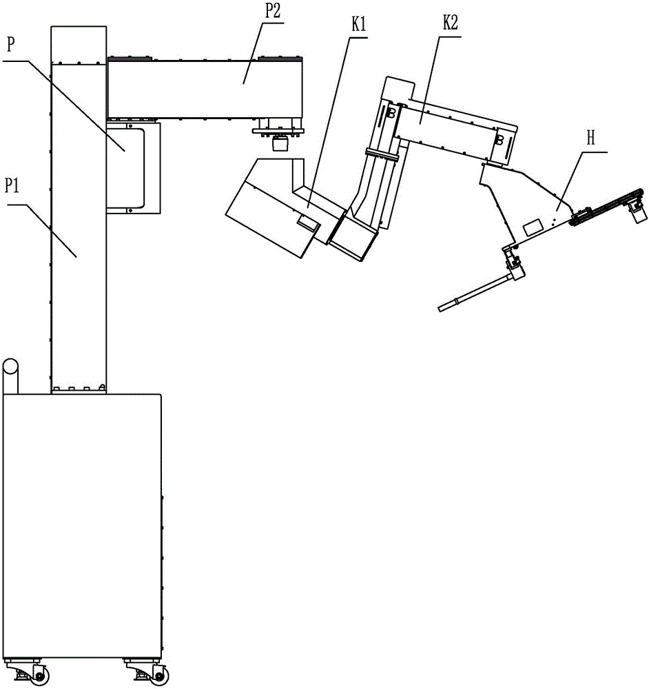
[0017] Specific implementation mode one: combine Figure 1-Figure 28 Explain that a minimally invasive robotic mirror-holding mechanical arm of this embodiment includes a passive arm P, a first joint K1, a second joint K2, and an endoscope clamping device; the passive arm P includes a vertical translation mechanism P1 and a joint connecting rod P2; the vertical translation mechanism P1 includes a base assembly 1, a guide rail assembly 2, and an outer interface connection assembly 3; the base assembly 1 includes a box body 1-1, a counterweight 1-2, and at least one optical axis assembly, at least one optical axis The assembly is arranged on the box body 1-1. The optical axis assembly includes the optical axis body 1-3 and two optical axis pressure rings 1-4, and the two optical axis pressure rings 1-4 are respectively fixedly connected to the box body 1- 1, the optical axis 1-3 passes through two optical axis pressure rings 1-4 from top to bottom and is fixedly connected in the...

specific Embodiment approach 2

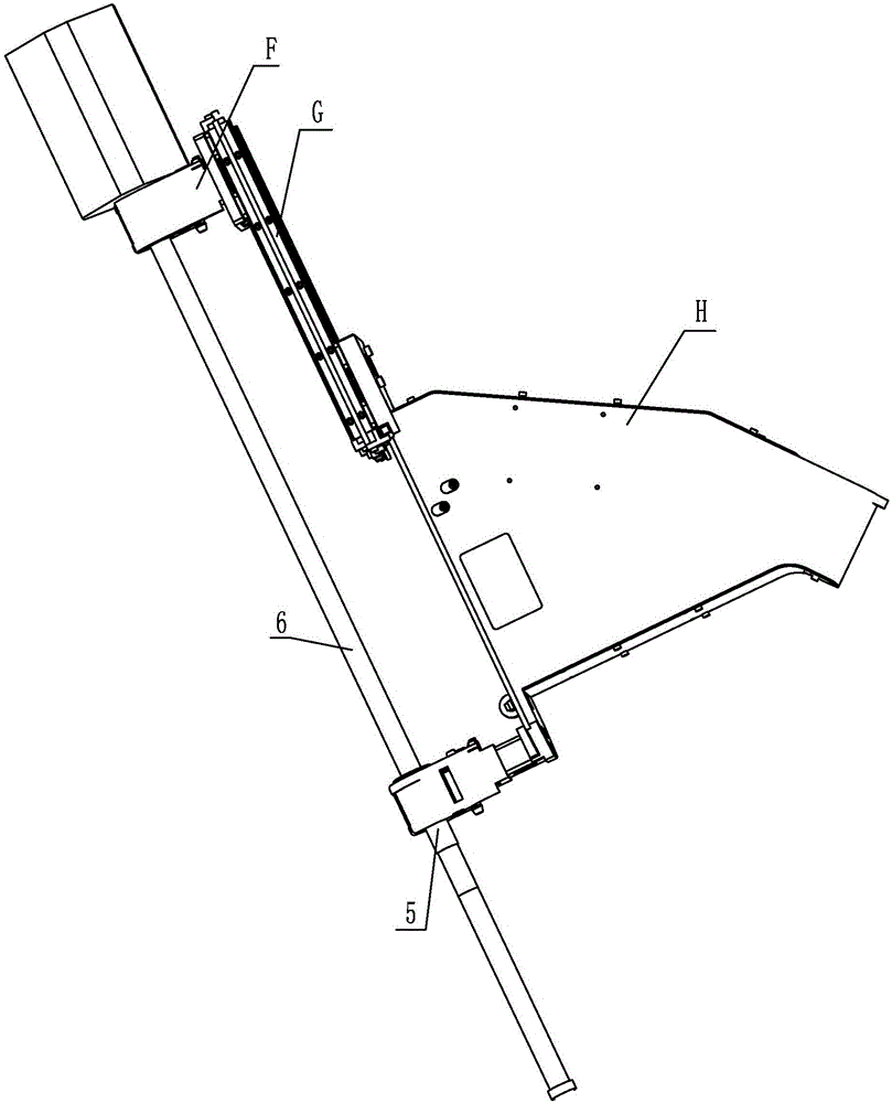
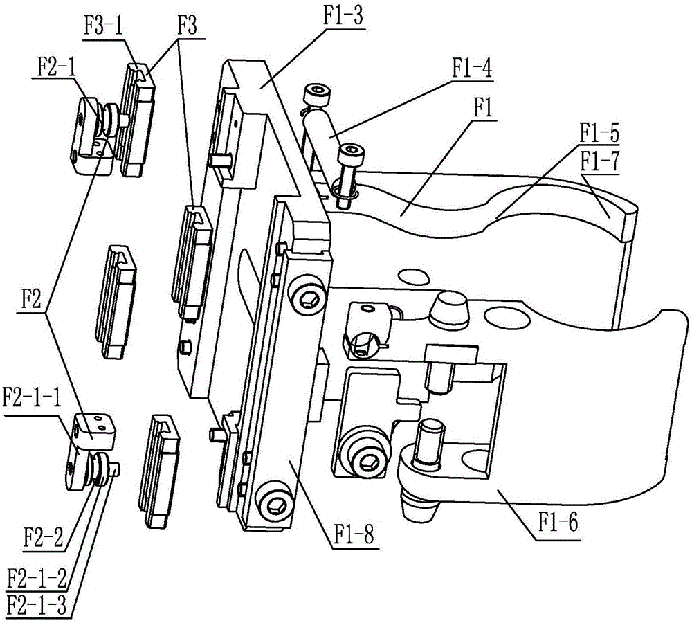
[0027] Specific implementation mode two: combination Figure 3-Figure 4 Explain that the endoscope holder F1 of this embodiment includes a clamping base F1-3, a spring F1-4, a fastening plate F1-5, a clamping movable arm F1-6 and a clamping fixed arm F1-7; A clamping fixed arm F1-7 is fixedly connected to the holding base F1-3, and a clamping movable arm F1-6 and a fastening pressure plate F1- 5. The clamping movable arm F1-6 can rotate on the clamping base F1-3, one end of the spring F1-4 is installed on the clamping movable arm F1-6, and the other end of the spring F1-4 is installed on the clamping fixed arm F1 On -7, a wedge-shaped block F1-6-1 cooperating with the fastening platen F1-5 is fixedly connected to the outer surface of the clamping movable arm F1-6, and the clamping base F1-1 of the poking clamper H3-1 3 Installed on the support frame H3-3. The clamping movable arm F1-6 of this embodiment is fixedly connected with a wedge-shaped block F1-6-1 cooperating with t...

specific Embodiment approach 3

[0028] Specific implementation mode three: combination Figure 9-Figure 10 Note that the poking holder H3-1 of this embodiment includes a clamping base F1-3, a spring F1-4, a fastening plate F1-5, a clamping movable arm F1-6 and a clamping fixed arm F1-7; The clamping fixed arm F1-7 is fixedly connected to the clamping base F1-3, and the clamping movable arm F1-6 and the fastening pressure plate F1 arranged in cooperation with the clamping fixed arm F1-7 are installed on the clamping base F1-3 -5, the clamping movable arm F1-6 can rotate on the clamping base F1-3, one end of the spring F1-4 is installed on the clamping movable arm F1-6, and the other end of the spring F1-4 is installed on the clamping fixed arm On F1-7, a wedge-shaped block F1-6-1 cooperating with the fastening plate F1-5 is fixedly connected to the outer surface of the clamping movable arm F1-6, and the clamping base F1 of the poking clamper H3-1 -3 is installed on the support frame H3-3. The clamping movab...


PUM


Abstract

A minimally invasive robot mirror-holding mechanical arm relates to an operation robot mechanical arm and solves problems of uneasy manual preoperative adjustments, difficult overall mechanism assembling and low rigidity due to large size of a present minimally invasive robot mechanical arm. The minimally invasive robot mirror-holding mechanical arm comprises a driven arm, a first joint, a second joint and an endoscope holding device. A vertical translation mechanism is formed by a pedestal assembly, a guide rail assembly and an external end joint connection assembly; the first joint is formed by a first driving assembly, a supporting housing, a transmission assembly and a first absolute encoder; the second joint is formed by an assembly rack and a second driving assembly; the endoscope holding device consists of an endoscope joint assembly, an auxiliary transition assembly and a power clamping assembly as well as a rope; and the endoscope joint assembly, the transition assembly and the power clamping assembly are orderly staggered and overlapped and connected with each other via the guide rail and the rope. The minimally invasive robot mirror-holding mechanical arm is applied to minimally invasive surgeries.

Description

technical field [0001] The invention relates to a mechanical arm for a surgical robot, in particular to a novel minimally invasive surgical robot mirror-holding mechanical arm, which belongs to the field of medical instruments. Background technique [0002] At present, minimally invasive surgery is a hot spot in medical technology research and is the future development trend of surgery. This is mainly due to the advantages of minimally invasive surgery, such as less trauma, shorter hospital stay, faster recovery, and fewer postoperative complications. However, traditional endoscopic surgery has many disadvantages, such as low operation accuracy, small field of view, small degree of freedom of operation, and doctors are prone to fatigue and trembling; with the development of science and technology, robotic medical assistance technology can well solve these problems. Robot-assisted technology can provide a 3D field of view, which is convenient for doctors to operate. Micro med...

Claims


Application Information

Patent Timeline
Patent Type & Authority Applications(China)
IPC IPC(8): A61B19/00
Inventor 潘博付宜利牛国君张福海封海波王树国
Owner 杭州唯精医疗机器人有限公司
Why Eureka
Try Eureka