Metal particle trap for direct-current gas-insulated power transmission line

A technology of metal particles and transmission lines, applied in the direction of electrode structure, electrostatic separation, power supply technology, etc., can solve the problems of difficult to control the direction of movement of DC GIL metal particles, difficult to capture metal particles, aging, etc., to solve aging and loss of viscosity Effect

Inactive Publication Date: 2015-12-16
NORTH CHINA ELECTRIC POWER UNIV (BAODING)
View PDF9 Cites 21 Cited by
  • Summary
  • Abstract
  • Description
  • Claims
  • Application Information

AI Technical Summary

Problems solved by technology

[0003] Due to the unipolar DC electric field inside the DC GIL, the moving metal particles run through the entire air gap and collide with the conductor, and have faster movement speed and frequency. Therefore, the DC GIL metal particle trap has to solve the following problems: Ordinary The metal particle trap is not

Method used


Image

  • Metal particle trap for direct-current gas-insulated power transmission line
  • Metal particle trap for direct-current gas-insulated power transmission line
  • Metal particle trap for direct-current gas-insulated power transmission line

Examples


Embodiment Construction

[0022] The present invention will be further described below in conjunction with the accompanying drawings.

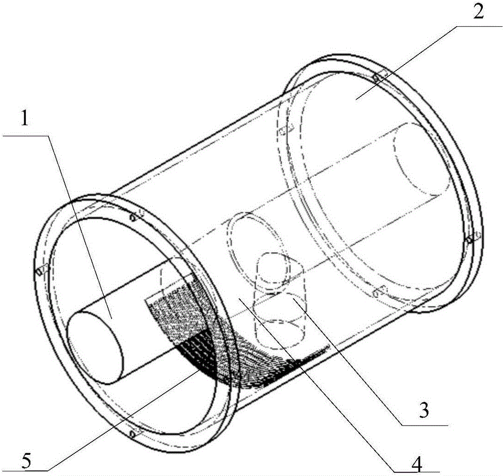
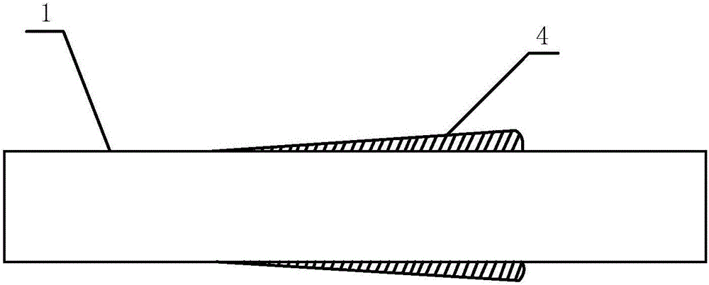
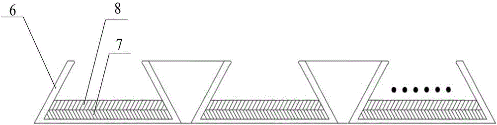
[0023] A metal particle catcher for DC gas insulated transmission lines, characterized in that it consists of two parts: a driving electrode and a metal particle capture tank; a DC GIL aluminum alloy conductor 1 and a DC GIL post insulator 3 Inside the casing 2, the driving electrode 4 is installed on the DC GIL aluminum alloy conductor 1 near the column insulator 3 for the DC GIL, and the metal particle capture groove 5 is installed at the bottom of the DC GIL cavity, so that the inclined surface of the driving electrode 4 faces the metal at the bottom. Particle capture tank 5, metal particle capture tank 5 is divided into 3 layers, from bottom to top are concave metal shielding tank 6, epoxy resin insulation pad 7, strong adhesive hot melt adhesive coating 8; among them, driving electrode 4 Use the electric field gradient and particle collision rebound angle to drive...


PUM


Abstract

The invention discloses a metal particle trap for a direct-current gas-insulated power transmission line. The metal particle trap is composed of a driving electrode and a metal particle trapping groove. A direct-current GIL aluminum alloy conductor and a pillar insulator for a direct current GIL are arranged inside a direct-current GIL aluminum alloy shell. The driving electrode is installed nearby the pillar insulator for the direct-current GIL on the direct-current GIL aluminum alloy conductor. The metal particle trapping groove is installed inside a direct-current GIL cavity, so that the inclined face of the driving electrode faces the bottom metal particle trapping groove. The metal particle trapping groove comprises three layers which are the inward-concave type metal shielding groove, an epoxy resin insulation pad and the high-viscidity hot melt adhesive coating in sequence from bottom to top. The metal particle trapping groove is used for capturing and limiting particles, the inward-concave type metal shielding groove in the bottommost layer generates a low electric field area, the epoxy resin insulation pad on the middle layer coats the whole bottom of the inward-concave type metal shielding groove, and the high-viscidity hot melt adhesive coating on the uppermost layer can control and trap particles moving at a high speed.

Description

technical field [0001] The invention belongs to the field of high-voltage transmission lines in electric power systems, and in particular relates to a metal particle catcher for DC gas-insulated transmission lines (GIL). Background technique [0002] in SF 6 or SF 6 / N 2 Due to the advantages of large transmission capacity, low loss, environmental friendliness and low maintenance cost, DC GIL with mixed gas as insulating gas has broad application prospects in power transmission occasions with high drop, difficult land acquisition, and complex crossing. A certain amount of metal particles will inevitably be produced during the manufacturing process of DC GIL and the operation of the equipment, and the metal particles will move in the equipment or attach to the surface of the electrode or insulator under the action of the electric field force, resulting in a gap between the conductor and the shell. Breakdown of the air gap or flashover of the insulator along the surface, th...

Claims


Application Information

Patent Timeline
IPC IPC(8): B03C3/34B03C3/40B03C3/66
Inventor 王健李伯涛李庆民
Owner NORTH CHINA ELECTRIC POWER UNIV (BAODING)
Why Eureka
Try Eureka