Rapid-heating heat treatment furnace

A heat treatment furnace and fast technology, applied in the field of heat treatment, can solve the problems of high use cost, temperature overshoot, applicability limitation, etc., and achieve the effects of high temperature and time control accuracy, fast heating and cooling speed, and convenient operation.

Active Publication Date: 2015-12-16
NINGBO INST OF MATERIALS TECH & ENG CHINESE ACADEMY OF SCI
View PDF8 Cites 11 Cited by
  • Summary
  • Abstract
  • Description
  • Claims
  • Application Information

AI Technical Summary

Problems solved by technology

However, the area of ​​laser heat treatment is limited by the size of the laser beam. The scanning plane method can realize large-area heat treatment, but the efficiency is low and the cost is high.
Both induction current and energized Joule heating also have problems such as serious temperature overshoot and low temperature control accuracy, and their applicability is limited.
[0006] For heat treatment with high heating and cooling speed and high temperature control precision, the above equipment can no longer meet the requirements. It is very necessary to develop a heat treatment device with more convenient operation and more precise temperature and time control.

Method used


Image

  • Rapid-heating heat treatment furnace
  • Rapid-heating heat treatment furnace
  • Rapid-heating heat treatment furnace

Examples


Embodiment Construction

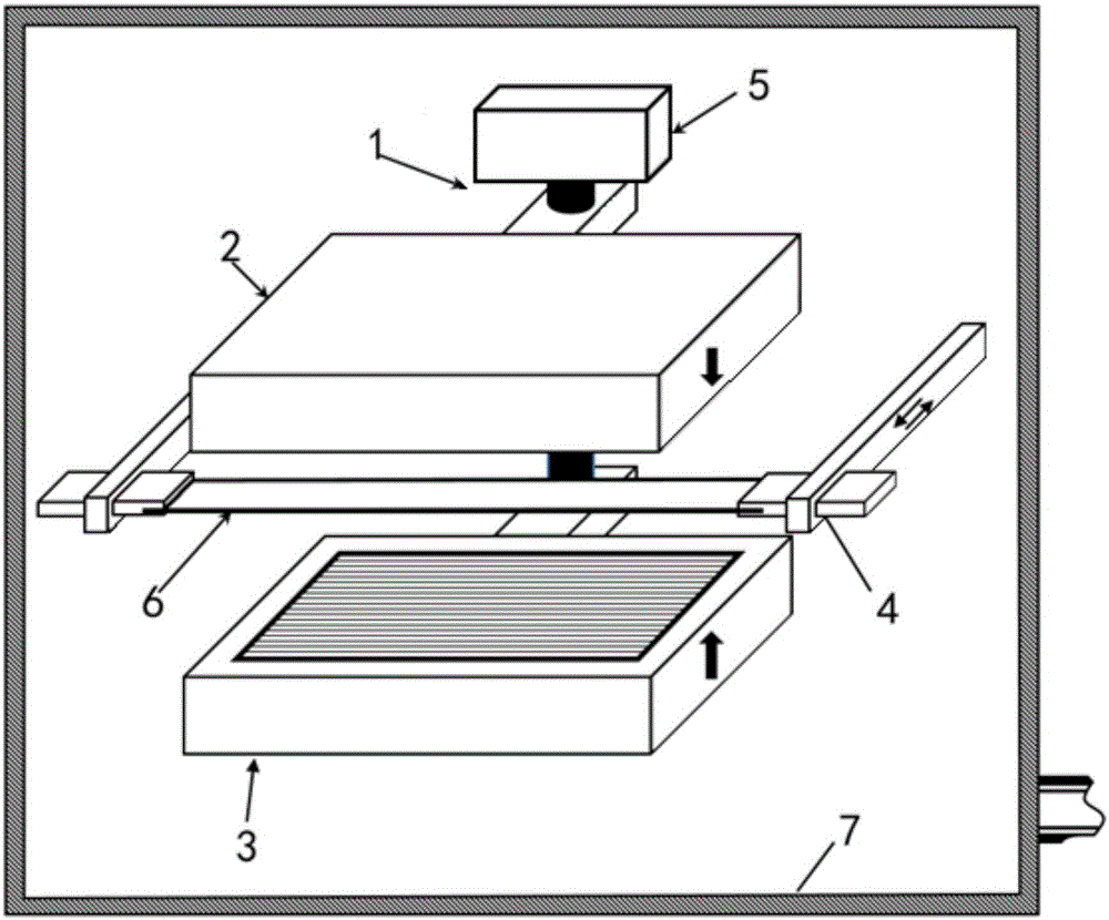
[0031] Such as figure 1 with 2 As shown, the heat treatment furnace for rapid temperature rise in this embodiment includes: a furnace cavity 7, an upper heating plate 2 and a lower heating plate 3 arranged oppositely in the furnace cavity 7 for opening and closing the upper heating plate 2 and the lower heating plate 3 The rapid lifting mechanism 1 is used to install the sample rack 4 of the sample, and the sample rack 4 can be stretched, and is used to drive the sample into and out of the radiation area between the upper heating plate 2 and the lower heating plate 3 .

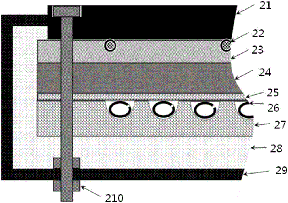
[0032]The upper and lower heating plates use a multi-layer composite structure to make the temperature of the heating surface uniform. The heat in the heating plate is provided by heating wires 26. There are multiple groups of heating wires 26. The number and distribution method can be set according to needs. This embodiment is installed in an evenly distributed manner. The heating wire 26 adjusts the power a...


PUM


Abstract

The invention discloses a rapid-heating heat treatment furnace which comprises a furnace cavity, a positioning piece and a heat source. The positioning piece is used for fixing a sample in the furnace cavity, and the heat source is used for heating the sample. The rapid-heating heat treatment furnace further comprises a heat source driving component and a positioning piece driving component. The heat source comprises two heating plates with opposite heating faces. The heat source driving component is used for driving the two heating plates to clamp the sample or be away from each other. A radiation area is formed between the two heating plates. The positioning piece driving component is used for driving the positioning piece to enable the sample to enter or exit from the radiation area. The two heating plates are adopted to carry out two-face synchronous contact heating on the sample, so that accurate control over the ultrahigh heating and cooling speed and heat treatment time is achieved by means of the low heat capacity and high heat conductivity of the thin-belt sample in a direct-contact manner, and meanwhile the cooling speed can be adjusted as needed. The rapid-heating heat treatment furnace has the beneficial effects of being high in heating and cooling speed, convenient to operate, high in temperature and time control precision and applicable to heat treatment of low-heat-capacity and high-heat-conductivity thin belt, thin film and powder samples.

Description

technical field [0001] The invention relates to the technical field of heat treatment, in particular to a heat treatment furnace for rapid temperature rise. Background technique [0002] Heat treatment is to heat the material to a certain temperature, keep it warm for a certain period of time, and then cool it down to room temperature or even lower at a certain speed, so as to achieve the purpose of improving the structure and physical and chemical properties of the material. Heat treatment has a very popular application in the heat treatment of various materials such as metals, ceramics, and glass. The heat treatment process of materials can have an important impact on the defects, stress, structure, and morphology of materials, and is the most commonly used process in material research and processing. [0003] With the advancement of heat treatment technology, the definition of heat treatment has expanded, the parameters that need to be controlled in the heat treatment pr...

Claims


Application Information

Patent Timeline
Patent Type & Authority Applications(China)
IPC IPC(8): F27D11/02B32B18/00B32B19/04B32B19/08B32B3/08
Inventor 王安定常春涛赵成亮王新敏贺爱娜岳士强
Owner NINGBO INST OF MATERIALS TECH & ENG CHINESE ACADEMY OF SCI
Why Eureka
Try Eureka