
Microbubble performance test and assessment experimental platform and test and assessment method thereof

A technology of an experimental platform and an evaluation method, applied in the microbubble performance test and evaluation experimental platform and its field of test evaluation, can solve the problems of inability to quantify the particle size distribution of microbubbles, single use and function, etc.

Inactive Publication Date: 2015-12-16
CHINA NAT OFFSHORE OIL CORP +2
View PDF9 Cites 8 Cited by
  • Summary
  • Abstract
  • Description
  • Claims
  • Application Information

AI Technical Summary

Problems solved by technology

However, the measurement methods based on PIV or PDA are more focused on the distribution of the velocity field or the distribution of the concentration field, and cannot quantify the particle size distribution of the microbubbles.
In general, the existing microbubble performance testing devices and methods not only cannot directly realize the on-line performance test and evaluation of industrial product-level microbubble generation technology, but also the purpose and function of the supporting experimental equipment are relatively single. Technical issues related to the influence of particle size change on the removal rate of pollutants

Method used


Image

  • Microbubble performance test and assessment experimental platform and test and assessment method thereof
  • Microbubble performance test and assessment experimental platform and test and assessment method thereof

Examples


Embodiment 1

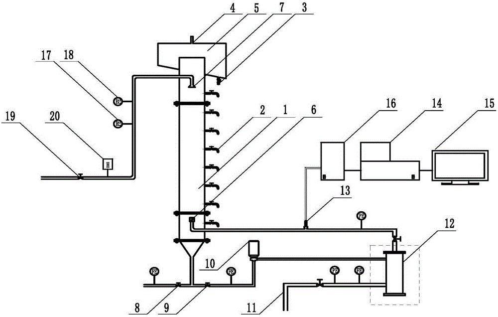
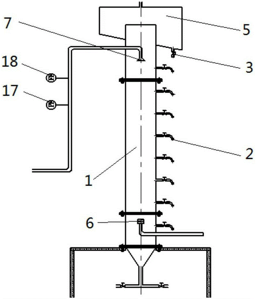
[0037] A microbubble performance test evaluation experimental platform, consisting of air flotation column 1, external drainage flow regulating gate valve 8, backflow gate valve 9, centrifugal pump 10, micro bubble generating device 12, laser particle size analyzer 14, computer 15, and sample addition controller 16. , Pressure gauge 17, flow meter 18, gas inlet 11, dosing metering pump 20 and other components. A scum collection tank 5 is provided on the top of the air flotation column 1, and a return water distribution unit 6 and a raw water distribution unit 7 are provided on the side wall of the air flotation column 1. The return water distribution unit 6 is located at the bottom of the air flotation column 1, and microbubbles are generated. The microbubbles and water-gas-liquid mixture produced by the device 12 are injected into the lower axial cross section of the air float column 1 through the reflux water distribution unit 6. The microbubble particle size test sampling po...

Embodiment 2

[0040] For a method for testing and evaluating microbubble performance, see Example 1. When testing and evaluating the microbubble performance test and evaluation experimental platform, first close the external drainage flow regulating gate valve 8 and the return gate valve 9 at the bottom of the air flotation column 1, and inject tap water into the air flotation column 1 through the raw water distribution unit 7 on the top of the air flotation column 1 When the liquid level in the air flotation column 1 reaches a certain height, specific gas air, nitrogen or natural gas is injected into the microbubble generating device 12 through the gas inlet 11, and then the return gate valve 9 is opened and the centrifugal pump 10 is turned on. The gas-liquid mixture with water is injected into the lower axial cross section of the air float column 1 through the reflux water distribution unit 6. After a period of time, the whole process can be in a stable equilibrium state. The gas-liquid ...

Embodiment 3

[0045] For a method for testing and evaluating microbubble performance, see Example 1. When the microbubble performance test evaluation experimental platform is used for test evaluation, the difference from Embodiment 2 is that the microbubble generating device 12 uses a tubular microbubble generator. The micro-bubble generator adopts the structure of "air distribution in the outer cavity-water in the inner cavity". Water enters the micro-bubble generator tangentially to form a swirling flow outside the microporous tube, and shear the airflow to generate microbubbles. In this example, not only the direct online test evaluation of the average particle size of the generated microbubbles was performed, but also the test evaluation of the oily sewage air flotation and degreasing effect was performed. The test of the average particle size of the microbubbles was the same as in Example 2. In order to test the degreasing effect of air flotation, samples were taken from the sampling po...


PUM

PropertyMeasurementUnit
Heightaaaaaaaaaa
The average particle sizeaaaaaaaaaa

Abstract

The invention belongs to the technical field of microbubble performance test and relates to a microbubble performance test and assessment experimental platform and a test and assessment method thereof. The microbubble performance test and assessment experimental platform is characterized in that a scum collection tank is arranged at the top of a flotation column, a bottom backflow gate valve is connected with a microbubble generation device which generates an air-liquid mixture of microbubbles and water, and the air-liquid mixture is injected to the lower portion of the flotation column through a backflow water distribution unit; a microbubble particle size test sampling port is connected with a laser particle analyzer through a sampling tube and a sample adding controller, and the laser particle analyzer is connected with a computer. The test and assessment method includes: according to a direct test and assessment method, completing online test of microbubble particle size distribution conditions by the aid of the laser particle analyzer and the computer; according to an indirect test and assessment method, injecting waste water into the flotation column, allowing part of bottom waste water to flow back into the flotation column through the microbubble generation device, and testing pollutants in different axial heights of the flotation column to complete indirect test and assessment. By the microbubble performance test and assessment experimental platform and the test and assessment method thereof, test and assessment of various microbubble generation techniques and product performances can be realized.

Description

Technical field [0001] The invention belongs to the technical field of microbubble performance testing, and particularly relates to a microbubble performance test evaluation experimental platform and a test evaluation method thereof. Background technique [0002] At present, microbubbles have been used to varying degrees in mineral flotation, medical ultrasound imaging, aquaculture, sewage treatment, enhanced gas-liquid mass transfer and other fields. In order for microbubbles to meet the technical requirements of various industries, it is necessary to test and evaluate their quality or particle size distribution before use. Existing bubble test and evaluation methods include conductivity probe method, microscopic imaging method, acoustic measurement method and laser measurement method. [0003] The conductivity probe method uses the difference in conductivity or refractive index between gas and liquid to test the size of the bubble. The bubble must be pierced during the measureme...

Claims


Application Information

Patent Timeline
IPC IPC(8): G01N15/02G01N15/00
Inventor 邵天泽孟迪陈家庆方相九姬宜朋李松杰车连发蔡小垒陈涛涛张喦郑秋生王涛霍志坚李树超张学添
Owner CHINA NAT OFFSHORE OIL CORP
Learn More