A method for optical visualization of low-dimensional nanomaterials

A low-dimensional nano and nanomaterial technology, applied in the field of nanomaterial characterization, which can solve the problems of complex methods and equipment, inability to remove markers, and short visualization time.

Active Publication Date: 2018-06-22
TSINGHUA UNIV
View PDF4 Cites 0 Cited by
  • Summary
  • Abstract
  • Description
  • Claims
  • Application Information

AI Technical Summary

Problems solved by technology

For example, Huang SM et al. (Huang S H, Qian Y, et al. J. Am. Chem. Soc. 2008, 130, 11860–11861) achieved optical visualization of single-walled carbon nanotubes by electrochemically depositing silver particles, but in It is carried out in the liquid phase, and electrodes need to be made on carbon nanotubes; Zhang RF, Zhang Y Y, et al. Nat. Optical observation, but the scope of application of this method is very narrow, and it is only effective for suspended carbon nanotubes. In practical applications, it is mainly carbon nanotubes on the surface of the substrate. In addition, titanium dioxide is not easy to remove, which affects the subsequent characterization and application of materials; Wang J T et al. (Wang J T, Li T Y, et al. Nano Lett. 2014, 14, 3527-3533) used the method of water vapor condensation to realize the optical visualization of carbon nanotubes on the substrate. The time is short, and the method is only applicable to the carbon nanotubes on the surface of the substrate, and it is not effective for the suspended carbon nanotubes
Chinese patent CN 101191794A proposes a method for preparing a fluorescent biosensor based on a one-dimensional nanostructure, but the surface treatment of the nanostructure is required, and the excited fluorescence is observed with a fluorescence microscope. The method and equipment are relatively complicated, and there is no mention Applicability of the method to 2D nanomaterials
However, the above-mentioned markers can only realize the optical visualization of suspended nanomaterials, but the marker substances used have certain toxicity and have no visualization / marking effect on the nanomaterials on the surface of the substrate, and the markers cannot be removed by heating, which will affect the further development of nanomaterials. application
[0005] In summary, so far, there is no labeling method with strong applicability (applicable to both substrate surface and suspended nanomaterials), strong controllability, and pollution-free, to realize the labeling method of nanomaterials under ordinary optical microscope or even naked eye. Direct observation under the environment, so as to assist the positioning, manipulation, other characterization (such as Raman spectrum characterization) and device construction of nanomaterials; in addition, the marker should be able to be removed in a controllable manner to avoid contamination of nanomaterials, thereby Does not affect its subsequent use

Method used


Image

  • A method for optical visualization of low-dimensional nanomaterials
  • A method for optical visualization of low-dimensional nanomaterials
  • A method for optical visualization of low-dimensional nanomaterials

Examples


Embodiment 1

[0041] Example 1. Optical visualization of a single carbon nanotube on a silica / silicon substrate using sublimated sulfur

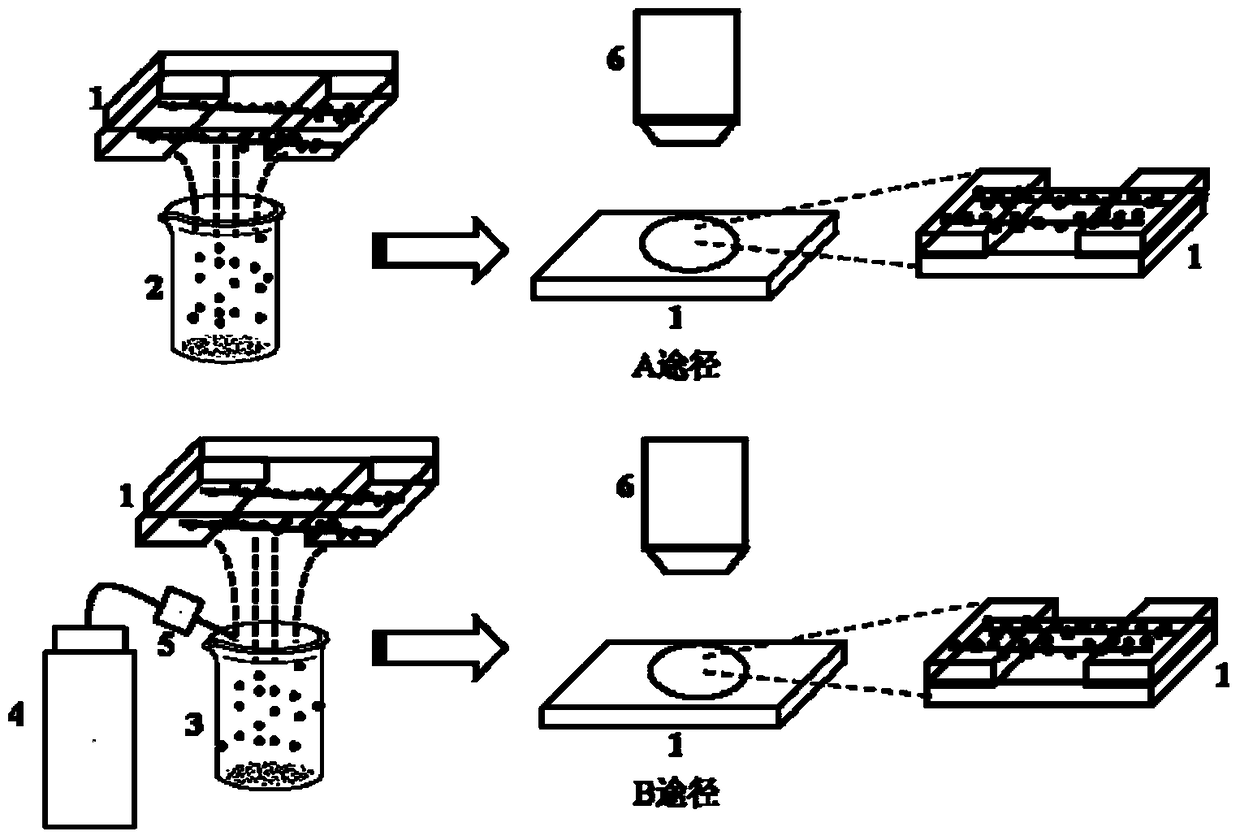
[0042] Specific process such as figure 1 As shown, the horizontal array of ultra-long carbon nanotubes grown on the silica / silicon substrate is prepared first, and then the sublimated sulfur is heated to 120 ° C by a heating platform. After the temperature is stable, the substrate with carbon nanotubes is turned upside down. Above the sublimated sulfur, take it off after 5 minutes, and observe it with an optical microscope.

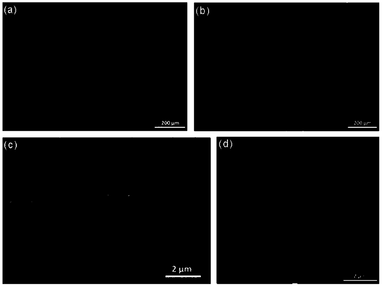
[0043] The optical photo of the sublimed sulfur-loaded carbon nanotubes prepared in this example is as follows figure 2 As shown, through optical photographs, scanning electron microscope photographs, and atomic force microscope photographs, it can be seen that sublimated sulfur is effectively supported on carbon nanotubes, and optical visualization of carbon nanotubes on a silica / silicon substrate is realized.

[0044] In this em...

Embodiment 2

[0046] Example 2. Optical visualization of suspended carbon nanotubes using sublimated sulfur

[0047] The specific process flow is the same as in Example 1. In this example, a substrate with slits is selected to grow carbon nanotubes, and the carbon nanotubes are in a suspended state at the slits, and the suspended carbon nanotubes are helpful for subsequent controllable manipulation. Place the substrate with suspended carbon nanotubes on top of sublimated sulfur at 120°C for 5 minutes, and then remove the sample for observation.

[0048] Optical photographs of the sublimed sulfur-loaded suspended carbon nanotubes prepared in this example are as follows Figure 4 As shown, it can be seen from optical photos and scanning electron microscope photos that the sublimated sulfur is effectively loaded on the suspended carbon nanotubes, and the optical visualization of the suspended carbon nanotubes is realized.

[0049] The suspended carbon nanotubes loaded with sublimed sulfur pre...

Embodiment 3

[0050] Example 3. Optical visualization of carbon nanotubes on a pure silicon substrate using sublimated sulfur

[0051] The specific process flow is the same as in Example 1. First, the horizontal array of ultra-long carbon nanotubes grown on a pure silicon substrate is prepared, and then the sublimated sulfur is heated to 120°C by a heating platform. The pure silicon substrate was placed upside down on the sublimated sulfur, removed after 5 minutes, and then observed with an optical microscope.

[0052] The optical photo of the sublimed sulfur-loaded carbon nanotubes prepared in this example is as follows Figure 5 As shown, the sublimated sulfur is effectively supported on the carbon nanotubes through the optical photographs, and the optical visualization of the carbon nanotubes on the pure silicon substrate is realized.


PUM

PropertyMeasurementUnit
sizeaaaaaaaaaa
sizeaaaaaaaaaa

Abstract

The invention discloses a method for achieving optical visualization of low-dimensional nanomaterials, and one or more sublimable / volatile markers are deposited on the nanomaterials. The method comprises the following steps: the marker is placed in a vessel, and is heated in the atmospheric environment; a substrate containing the low-dimensional nanomaterials is placed above the marker, and the marker is deposited on the nanomaterials, and the substrate is taken down and observed by utilizing an optical microscope. The marker is selected from one or more of sublimed sulfur, metallo-organic compound, inorganic ammonium salt, carbamide, ammonium persulfate, paraffin or fatty acid. Compared with the prior art, the method is simple and high in applicability and controllability, the low-dimensional nanomaterials do not need to be pretreated, and the location of the nanomaterials under a common optical microscope is realized; the laboratory investigation and industrial manufacture as well as application of the nanomaterials are greatly convenient; the adopted marker can be controllably removed, pollution and destruction of nanomaterials do not exist, and the later use of the nanomaterials is not influenced.

Description

technical field [0001] The invention relates to a method for realizing direct observation of low-dimensional nanomaterials under an ordinary optical microscope or even naked eyes, and belongs to the technical field of nanomaterial characterization. Background technique [0002] Nanomaterials refer to materials with at least one dimension in the nanoscale range (1-100nm) in the microstructure or composed of them as basic units, and have been developed rapidly since the 1980s. Nanomaterials have unique structures and excellent properties such as force, electricity, heat, magnetism, and light, and have broad application prospects in nanoelectronic devices, biosensors, and optical devices. One-dimensional nanomaterials mainly include nanowires, nanotubes, nanobelts, nanorods, etc.; two-dimensional nanomaterials mainly include nanofilms, such as graphene. The development of nanomaterials has promoted and improved corresponding characterization techniques, such as scanning electr...

Claims


Application Information

Patent Timeline
Patent Type & Authority Patents(China)
IPC IPC(8): G01N21/00
Inventor 张莹莹蹇木强
Owner TSINGHUA UNIV
Why Eureka
Try Eureka