Device utilizing underground superficial layer soil temperature for tracking solar declination angles and adjusting method

A technology for soil temperature and tracking the sun, applied in the field of solar energy utilization, can solve the problems of large tracking accuracy, low accuracy, fast response speed, etc., and achieve the effects of good change consistency, high tracking accuracy, and small tracking accuracy.

Inactive Publication Date: 2015-12-16
ANHUI JOYFULL INFORMATION SCI & TECH
View PDF1 Cites 3 Cited by
  • Summary
  • Abstract
  • Description
  • Claims
  • Application Information

AI Technical Summary

Problems solved by technology

This technology obviously has the following problems: 1. The altitude angle of the sun changes all the time from sunrise to sunset, from only a few degrees at sunrise to 70 or 80 degrees at noon and decreases with the increase of latitude. And then back to the altitude angle of a few degrees at sunset, the range of change is large, the speed of change is fast, and it varies with the seasons, so the tracking of the sun's altitude angle requires fast response, and the temperature of the fluid in the expansion tank changes Due to the influence and limitation of the thermal resistance of heat transfer and the thermal inertia of the device itself, the rate of temperature change is slow, and it is difficult for the active device driven by the temperature change of the fluid in the expansion tank to track the change rate of the solar altitude angle in time, resulting in a large tracking error
[0004] 2. The change consistency between the sun altitude angle and the ambient temperature is poor
The change of ambient temperature has a short cycle in one day, a medium-term cycle in two periods of strong convective weather changes, a long cycle in a year, and a short cycle in the environment temperature and solar altitude angle. The difference in characteristics; in the middle period, after each strong cooling weather, even within a few days, the ambient temperature will rise rapidly with the fine weather, and the ambient temperature changes greatly in the preceding and following days, while the sun The change law of the altitude angle is basically unchanged; in the long period, the average temperature in summer is very high, while the average temperature in

Method used


Image

  • Device utilizing underground superficial layer soil temperature for tracking solar declination angles and adjusting method
  • Device utilizing underground superficial layer soil temperature for tracking solar declination angles and adjusting method
  • Device utilizing underground superficial layer soil temperature for tracking solar declination angles and adjusting method

Examples


Example Embodiment

[0033] Example 1

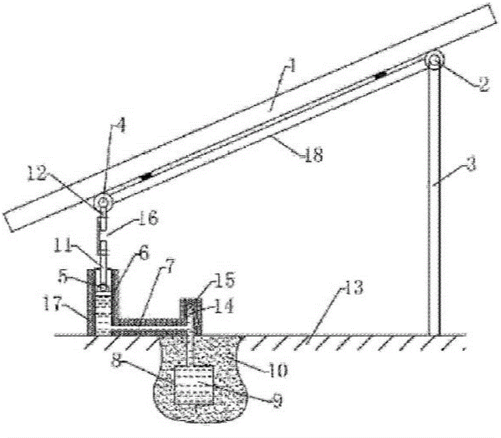
[0034] like figure 1 As shown, the device is placed in the north-south direction, and there are two sets of support rods in the north and south: the north support rod 3 and the south support rod 12, and the telescopic hydraulic cylinder 6 and its piston rod 11 are connected in series on the south support rod 12, and the hydraulic cylinder 6 The inner cavity of the inner cavity communicates with the inner cavity of the thermal expansion tank 8 buried in the shallow underground soil 10, the inner cavity of the hydraulic cylinder 6 and the thermal expansion tank 8 is filled with a thermal expansion fluid medium 9, and the bracket under the solar receiver 1 18. In the polygonal structure composed of the north support rod 3 , the south support rod 12 and the base 13 , there are three rotating movable nodes, and the south support rod 12 is provided with a screw-adjustable intervening temperature compensation adjustment device 16 .

[0035] The buried depth of the...

Example Embodiment

[0037] Example 2

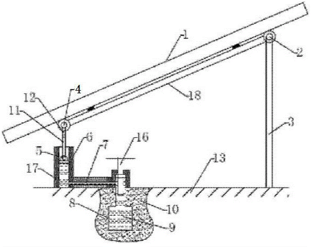
[0038] like figure 2 As shown, on the basis of Embodiment 1, the screw hydraulic type interventional temperature compensation adjustment device 16 is refitted on the thermal expansion tank 8. The buried depth of the thermal expansion tank 8 in the soil 10 is 30 cm, and the hydraulic cylinder 6 passes through the pressure guiding hose. 7 is in communication with the thermal expansion tank 8. This device does not have a separate liquid injection and discharge port 14 and valve 15, but uses a screw hydraulic type interventional temperature compensation adjustment device 16 as the liquid injection and discharge port 14 and valve 15. The outer surface of the above device is provided with a thermal insulation layer 17 to reduce the influence of the ambient temperature on the temperature of the thermal expansion fluid medium 9 .

[0039] The intervening temperature compensation adjustment method is changed to: between June 1st and August 31st every year, the sout...

Example Embodiment

[0040] Example 3

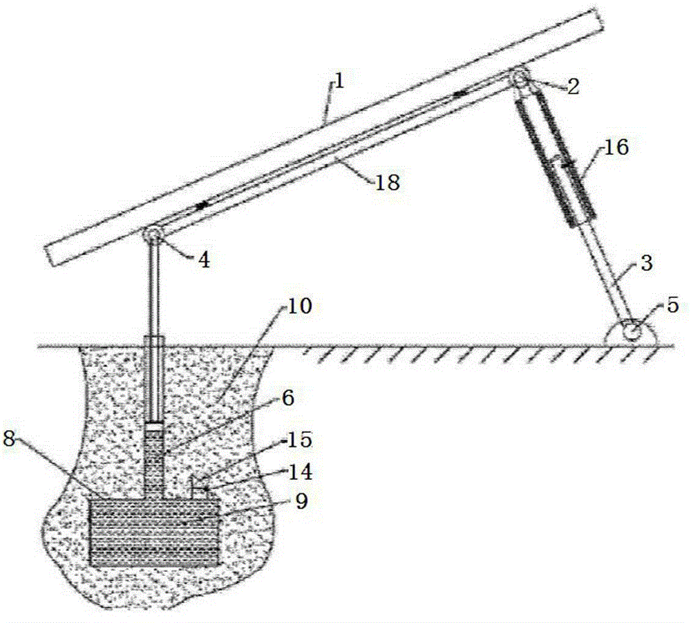
[0041] like image 3 As shown, on the basis of Example 1, the interventional temperature compensation adjustment device 16 is changed to a sliding sleeve adjustment device, the interventional temperature compensation adjustment device 16 is refitted on the north support rod 3, and the thermal expansion tank 8 in the soil 10 The buried depth is 100cm, the hydraulic cylinder 6 is directly connected with the thermal expansion tank 8, the liquid injection and discharge port 14 and the valve 15 are changed to the thermal expansion tank 8, and the outer surface of the device above the ground is not provided with an insulating layer 17.

[0042] The intervening temperature compensation adjustment method is changed to: between June 1st and August 31st each year, the north support rod 3 is extended successively in 3 times through the interventional temperature compensation adjustment device 16, so as to adjust the size of the solar receiver 1 The inclination angle i...


PUM


Abstract

The invention provides a device utilizing underground superficial layer soil temperature for tracking solar declination angles and an adjusting method. According to the invention, the device is driven to track the solar declination angles by utilizing the change rule of the underground superficial layer soil temperature, so that tracking precision is improved and tracking cost is reduced. Inner pressure intensity caused by thermal expansion and cold contraction of a thermal expansion fluid medium subjected to the effect of underground superficial layer soil temperature change drives a piston of a hydraulic pressure cylinder to move in a reciprocating manner. The piston rod pushes a rotary support to track the change of the solar declination angles. Besides, an interference-type temperature compensation adjusting device or an automatic temperature adjustment adjusting device used for compensating the phase difference between the underground superficial layer soil temperature and the solar declination angle change rule are added in the tracking device. According to the adjusting method, the inclination angle of a solar power receiver is reduced during periods around the summer solstice and the winter solstice for achieving the compensation of errors due to delay caused by winter low temperature. Moreover, no manual adjustment is required for the automatic temperature compensation adjusting device and comparatively high-precision tracking can be ensured all the year.

Description

technical field [0001] The invention belongs to solar energy utilization technology. Background technique [0002] The direct sunlight incident light at a certain point on the earth is changing at any time. In order to utilize the direct solar radiant energy as much as possible, the solar energy utilization device is required to be equipped with a device capable of tracking the position of the sun. Most solar tracking devices are mainly electric drive devices. Such devices have high tracking accuracy, but consume energy during the tracking process, and the operation and maintenance costs are high. The present invention realizes the use of regular changes in underground shallow soil temperature to track changes in the sun's declination angle. The tracking device does not consume energy and has low cost , easy to maintain, has high application prospects and market value. [0003] The literature about the device and adjustment method for tracking the sun's declination angle by...

Claims


Application Information

Patent Timeline
IPC IPC(8): G05D3/12
Inventor 朱卫国叶剑鸣印金汝
Owner ANHUI JOYFULL INFORMATION SCI & TECH
Why Eureka
Try Eureka