
High-voltage cable leading-in device of field emission electron gun

A technology of high-voltage cables and lead-in devices, applied in circuits, discharge tubes, electrical components, etc., can solve the problems of insufficient ground withstand voltage, insufficient withstand voltage of high-voltage cables, and easy damage of high-voltage cables of equipment, and achieve stable quality and improve. The effect of imaging quality and equipment safety

Inactive Publication Date: 2015-12-16
KYKY TECH
View PDF6 Cites 0 Cited by
  • Summary
  • Abstract
  • Description
  • Claims
  • Application Information

AI Technical Summary

Problems solved by technology

[0005] Therefore, the technical problem to be solved by the present invention is to overcome that the lead-in device of the high-voltage cable of the existing field emission electron gun is likely to cause insufficient withstand voltage value relative to the earth, insufficient withstand voltage value between the poles of the high-voltage cable, and then cause the equipment to not run stably and the high-voltage cable to fail. Introduce technical defects that can easily destroy the vacuum degree of the electron gun chamber and affect the imaging quality of the scanning electron microscope; thereby providing a method that can meet the withstand voltage value relative to the earth and the high-voltage cable inter-electrode withstand voltage value, so that the equipment can run stably and the introduction of high-voltage cables will not The introduction device for improving the imaging quality of the scanning electron microscope by destroying the vacuum degree of the electron gun chamber

Method used


Image

  • High-voltage cable leading-in device of field emission electron gun
  • High-voltage cable leading-in device of field emission electron gun

Examples


Embodiment 1

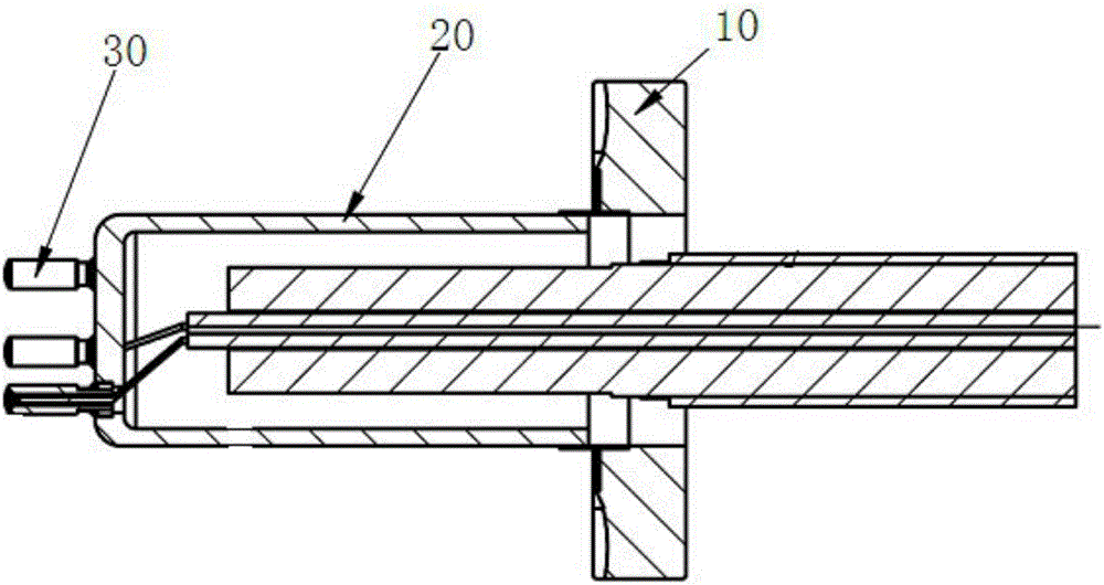
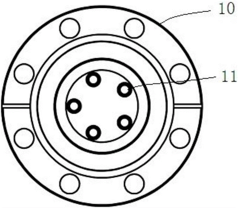
[0029] This embodiment provides an introduction device for a high-voltage cable of a field emission electron gun, which is used to provide working power for the field emission electron gun, wherein the field emission electron gun is arranged in an electron gun chamber with an ultra-high vacuum.

[0030] refer to figure 1 with figure 2 , the lead-in device of the field emission electron gun high-voltage cable of the present embodiment is installed in the flange 10 both sides in the electron gun chamber, and the high-voltage power supply input end is that the multi-strand high-voltage cable is introduced into the electron gun chamber by the outside of the flange 10; The end, that is, the high-voltage sealing electrode 30 is located on the inside of the flange 10, one end of which is coupled to the high-voltage cable, and the other end is coupled to the relevant components of the field emission electron gun, and the relevant components specifically refer to the emitter cathode, ...


PUM


Abstract

The invention discloses a high-voltage cable leading-in device of a field emission electron gun. The leading-in device comprises an insulated sealing member, a high-voltage cable, a high-voltage power reception end and an insulated filler, wherein the insulated sealing member is mounted in a chamber of the electron gun, and comprises an installation cavity and a leading-in port, the high-voltage cable includes multiple strands, extends into the installation cavity of the insulated sealing member via the leading-in port, and is used to lead external power supply into the chamber of the electron gun, the two ends of the high-voltage power reception end are coupled to the high-voltage cable and the field emission electron gun respectively, and the insulated filler is filled among the different strands of high-voltage cable, between the high-voltage cable and the inner wall of the insulated sealing member, and in the leading-in port. It can be ensured that certain withstanding voltage exists among the different strands of high-voltage cable, gas is prevented from entering the chamber of the electron gun, and an vacuum environment of the chamber of the electron gun is not damaged.

Description

technical field [0001] The invention relates to a lead-in device for a high-voltage cable of a field emission electron gun, and belongs to the technical field of high-voltage power lead-in equipment. Background technique [0002] Scanning electron microscope is a kind of electron optical instrument, which uses focused electron beam to scan the surface of the sample line by line, so that the electron beam bombards the surface of the sample to generate secondary electrons, and uses the above secondary electrons to present the surface morphology of the sample. The resolution of scanning electron microscope images can reach the nanometer level or even better than 1.0 nanometers, and it is widely used in new materials, new energy, national defense, scientific research and other fields. [0003] The above-mentioned focused electron beam is provided by the field emission electron gun on the scanning electron microscope, and the field emission electron gun needs to be introduced int...

Claims


Application Information

Patent Timeline
IPC IPC(8): H01J37/248
Inventor 孙占峰
Owner KYKY TECH
Learn More