Automatic chamfer turning lathe

An automatic turning and chamfering technology, applied in turning equipment, turning equipment, metal processing equipment, etc., to achieve the effect of simple structure and convenient use

Inactive Publication Date: 2015-12-23
苏州市豪基工具制造有限公司
View PDF6 Cites 0 Cited by
  • Summary
  • Abstract
  • Description
  • Claims
  • Application Information

AI Technical Summary

Problems solved by technology

[0006] With the rapid development of lathes, it has been suitable for mass production, but there is no automatic chamfering lathe that can be used for assembly line production.

Method used


Image

  • Automatic chamfer turning lathe

Examples


Embodiment Construction

[0014] The present invention will be further described below in conjunction with the accompanying drawings.

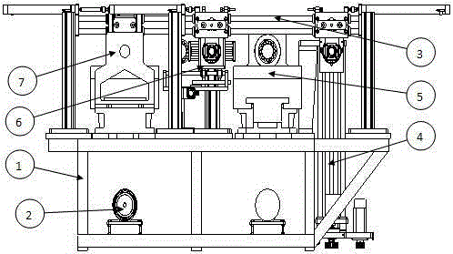
[0015] A lathe for automatic chamfering, including a bed body 1, a motor 2, a crossbeam 3, a lifting mechanism 4, a rough machining station 5, a chamfering station 6, and a finishing station 7. It is characterized in that the motor 2 is set on the bed body 1 Below, a lifting mechanism 4 is provided on one side of the bed body 1, a crossbeam 3 is provided above the bed body 1, and a roughing station 5, a chamfering station 6, and a finishing station are arranged sequentially below the crossbeam 3 from the side of the lifting mechanism 4. The position 7 and the chamfering position 6 are internally provided with a driving device, and the roughing position 5 and the finishing position 7 are driven by the motor 2 at the bottom of the bed body 1 . There are two motors 2. The motor 2 corresponding to the rough machining station 5 is in the opposite direction to the motor 2 c...


PUM


Abstract

The invention relates to an automatic chamfer turning lathe. The automatic chamfer turning lathe comprises a lathe body, motors, a beam, a lifting mechanism, a rough machining station, a chamfering station and a finish machining station, and is characterized in that the motors are arranged below the lathe body, the lifting mechanism is arranged on one side of the lathe body, the beam is arranged on the lathe body, the rough machining station, the chamfering station and the finish machining station are sequentially arranged at the portions, from one side of the lifting mechanism, below the beam, the chamfering station is internally provided with a driving device, and the rough machining station and the finish machining station are driven by the motor at the bottom of the lathe body. According to the automatic chamfer turning lathe, as the beam is in a double-track type, machining devices on the rough machining station, the chamfering station and the finish machining station are convenient to position; in addition, as the rough machining station and the finish machining station are driven by the motors arranged below the lathe body, the problem of the machining power can be effectively solved; as the directions of the two motors are opposite, the transmitting wiring problem caused when the motors are arranged in the same direction can be solved.

Description

technical field [0001] The invention relates to the field of mechanical equipment, in particular to a lathe for automatic chamfering. Background technique [0002] A lathe is a machine tool that mainly uses a turning tool to turn a rotating workpiece. Drills, reamers, reamers, taps, dies and knurling tools can also be used for corresponding processing on the lathe. The ancient lathe was pulled by hand or pedal, the workpiece was rotated through the rope, and the cutting tool was held in hand. [0003] In 1797, Mozley, a British mechanical inventor, created a modern lathe with a screw drive tool holder, and in 1800, the exchange gear was used to change the feed speed and the pitch of the processed thread. In 1817, another Englishman, Roberts, used a four-stage pulley and back wheel mechanism to change the spindle speed. [0004] In order to improve the degree of mechanization and automation, in 1845, Fitch in the United States invented the turret lathe. In 1848, the retur...

Claims


Application Information

Patent Timeline
IPC IPC(8): B23B3/30
CPCB23B3/30B23B2220/08B23B2220/24B23B2220/44
Inventor 王俊
Owner 苏州市豪基工具制造有限公司
Why Eureka
Try Eureka