
Machining device and machining method of forming hole

A processing device and processing method technology, applied in the direction of fixed grinding wheel device, grinding drive device, metal processing equipment, etc., can solve the problems of laborious, low processing efficiency of forming holes, size difference exceeding the process range, etc., to improve processing production Efficiency and pass rate, save grinding tool setting time, solve the effect of batch processing

Inactive Publication Date: 2015-12-23
自贡中兴耐磨新材料有限公司
View PDF5 Cites 3 Cited by
  • Summary
  • Abstract
  • Description
  • Claims
  • Application Information

AI Technical Summary

Problems solved by technology

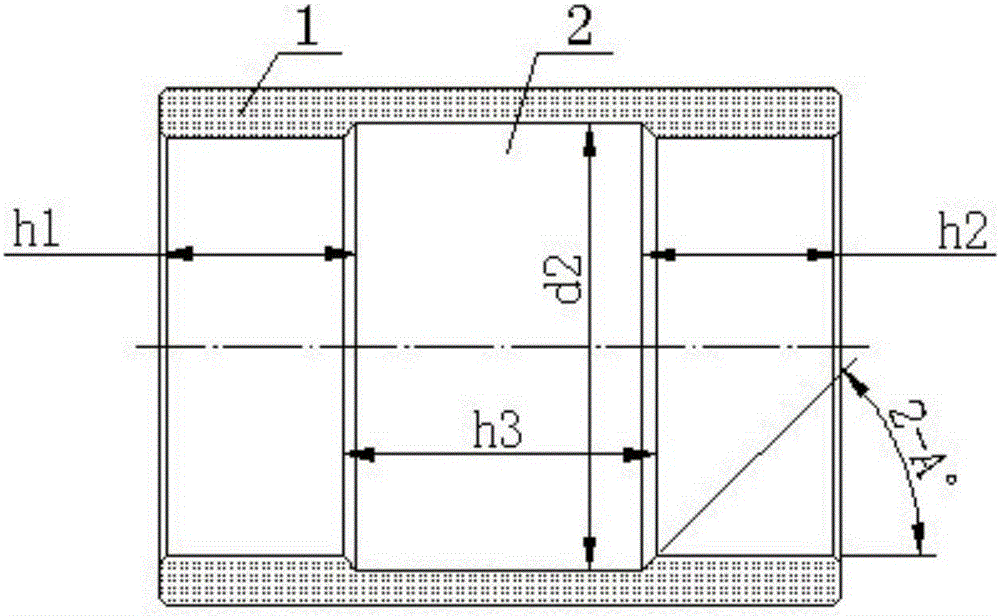
[0005] First, during processing, the height consistency of the processed parts is required to be high, and the dimensional consistency must be within ±0.01, otherwise, the distance between the two ends of the processed forming hole and the end faces of the adjacent processed parts will be The size difference between h1 and h2 exceeds the process range, resulting in defective processing;
[0006] Second, when the forming hole is wider, the grinding wheel used also needs to be widened accordingly. During grinding, as the width of the grinding wheel increases, the grinding force also increases, which easily causes the deformation of the grinding wheel rod. It is difficult to ensure that the diameter of the forming hole Φd2 is qualified; and in order to reduce the grinding force, the feed speed needs to be controlled very small, which in turn leads to low processing efficiency of the forming hole
[0007] Third, for the grinding of cemented carbide parts, diamond grinding wheels are used, but for the dressing of diamond grinding wheels, it is impossible to directly dress with a diamond pen, and only the way of dressing outside the machine can be used.
For forming holes with such high precision, during processing, the grinding wheel needs to be trimmed every time 5 parts are processed. Each time the grinding wheel is trimmed, the grinding wheel must be removed together with the grinding wheel rod. When replacing the grinding wheel, due to the different length and width of the grinding wheel, It is very time-consuming and labor-intensive to re-set the tool after trimming, and the processing efficiency is very low

Method used


Image

  • Machining device and machining method of forming hole
  • Machining device and machining method of forming hole
  • Machining device and machining method of forming hole

Examples


Embodiment Construction

[0027] In order to make the object, technical solution and advantages of the present invention clearer, the present invention will be described in detail below in conjunction with the accompanying drawings and specific embodiments. It should be understood that the specific embodiments described here are only used to explain the present invention, not to limit the present invention.

[0028] like figure 1 The hard alloy processing part 1 shown has a through hole in its center, and a section of forming hole 2 is arranged on the through hole. Hole diameter, the distance between its left end surface and the left end surface of the adjacent processing part 1 is h1, the distance between its right end surface and the right end surface of the adjacent processing part 1 is h2, the forming The width dimension of the hole 2 is h3, the port portion thereof is in the shape of a truncated cone, and the angle of the taper surface thereof is A°. Since the process qualification requirements ...


PUM


Abstract

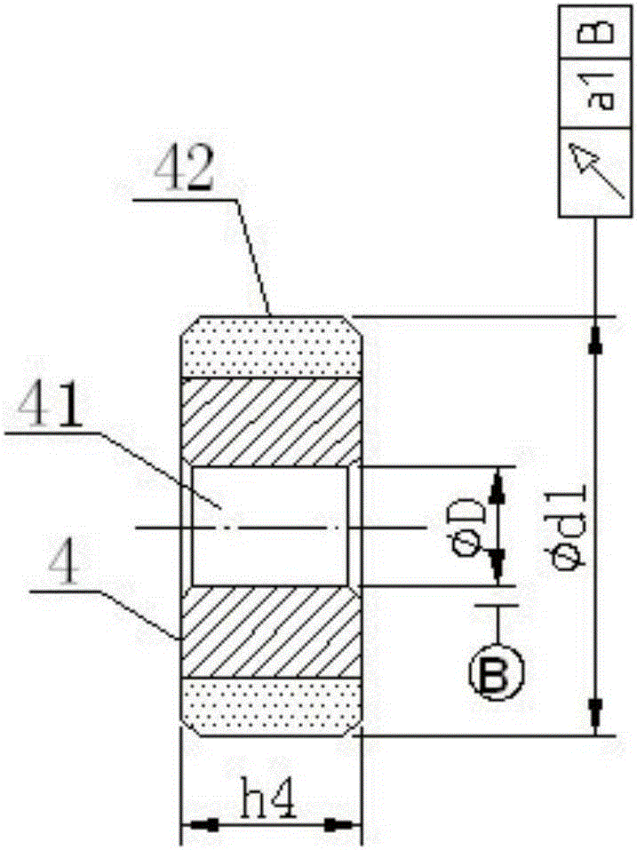
The invention provides a machining device and method of a forming hole. The machining device comprises a grinding wheel (4) and a grinding wheel rod (5), wherein the grinding wheel (4) is fixedly connected with a grinding wheel mounting part (52) at one end of the grinding wheel rod (5); a grinding wheel mounting hole (41) in the grinding wheel (4) is in interference fit with the grinding wheel mounting part (52) on the grinding wheel rod (5); the other end of the grinding wheel rod (5) is provided with a grinding wheel rod clamping part (51); the axial width of the grinding wheel (4) is smaller than the axial width of the forming hole; the diameter tolerance of the grinding wheel mounting hole (41) is 0-0.01 mm; and the diameter tolerance of the grinding wheel mounting part (52) is 0.01-0.02. When the machining device is used for grinding the forming hole, the machining of the forming hole by a longitudinal reciprocating and transverse feeding grinding mode can be realized, so that a lot of grinding wheel finishing time and grinding tool setting time are saved, and the machining productivity of the forming hole is greatly improved.

Description

technical field [0001] The invention relates to the technical field of machining of cemented carbide parts, in particular to a processing device and a processing method for a forming hole on a cemented carbide part. Background technique [0002] like figure 1 The forming hole 2 on the hard alloy machined part 1 shown has high dimensional accuracy and high positional accuracy, the width dimension h3±0.02, the diameter of the forming hole 2 φd2±0.02, and the angle of the taper surface of the port part of the forming hole 2 requires A °±0.3°, and the distances h1 and h2 between the two end faces of the forming hole 2 and the two end faces of the adjacent processed part 1 are 0.02 apart. [0003] In order to process the above-mentioned forming holes, most of the existing processing methods adopt the cutting and grinding mode of the forming grinding wheel, that is, after the forming grinding wheel is inserted into the through hole on the processed part, the grinding wheel only p...

Claims


Application Information

Patent Timeline
Patent Type & Authority Applications(China)
IPC IPC(8): B24B5/48B24B47/20B24B45/00
CPCB24B5/48B24B45/00B24B45/003B24B47/20
Inventor 钟健陈桂芳
Owner 自贡中兴耐磨新材料有限公司
Learn More