DMD module, DLP machine and DLP projection device

A component and fixing technology, applied in the field of optics and projection, can solve the problems of poor contact between the DMD chip and the driver board, the image quality of the optical system, the relative position displacement of the components, etc. quality effect

Inactive Publication Date: 2017-05-10
HISENSE
View PDF9 Cites 11 Cited by
  • Summary
  • Abstract
  • Description
  • Claims
  • Application Information

AI Technical Summary

Problems solved by technology

Please see attached figure 1 In the prior art, the heat sink is directly locked with the driver board and the DMD chip by hard connection through screws. However, since the heat sink is generally large in size and heavy, when it is assembled with the driver board and the DMD chip It is easy to cause uneven fixed force or the relative position displacement between the components after being interfered by other structural parts such as the housing, which will lead to poor contact between the DMD chip and the driver board, making the image formed by the final output of the optical system appear. picture quality problem

Method used


Image

  • DMD module, DLP machine and DLP projection device
  • DMD module, DLP machine and DLP projection device
  • DMD module, DLP machine and DLP projection device

Examples


Embodiment Construction

[0031] The present invention will be further described below with reference to the accompanying drawings and exemplary embodiments, wherein the same reference numerals in the accompanying drawings all refer to the same components. Also, detailed descriptions of known arts will be omitted if they are unnecessary to illustrate the features of the present invention.

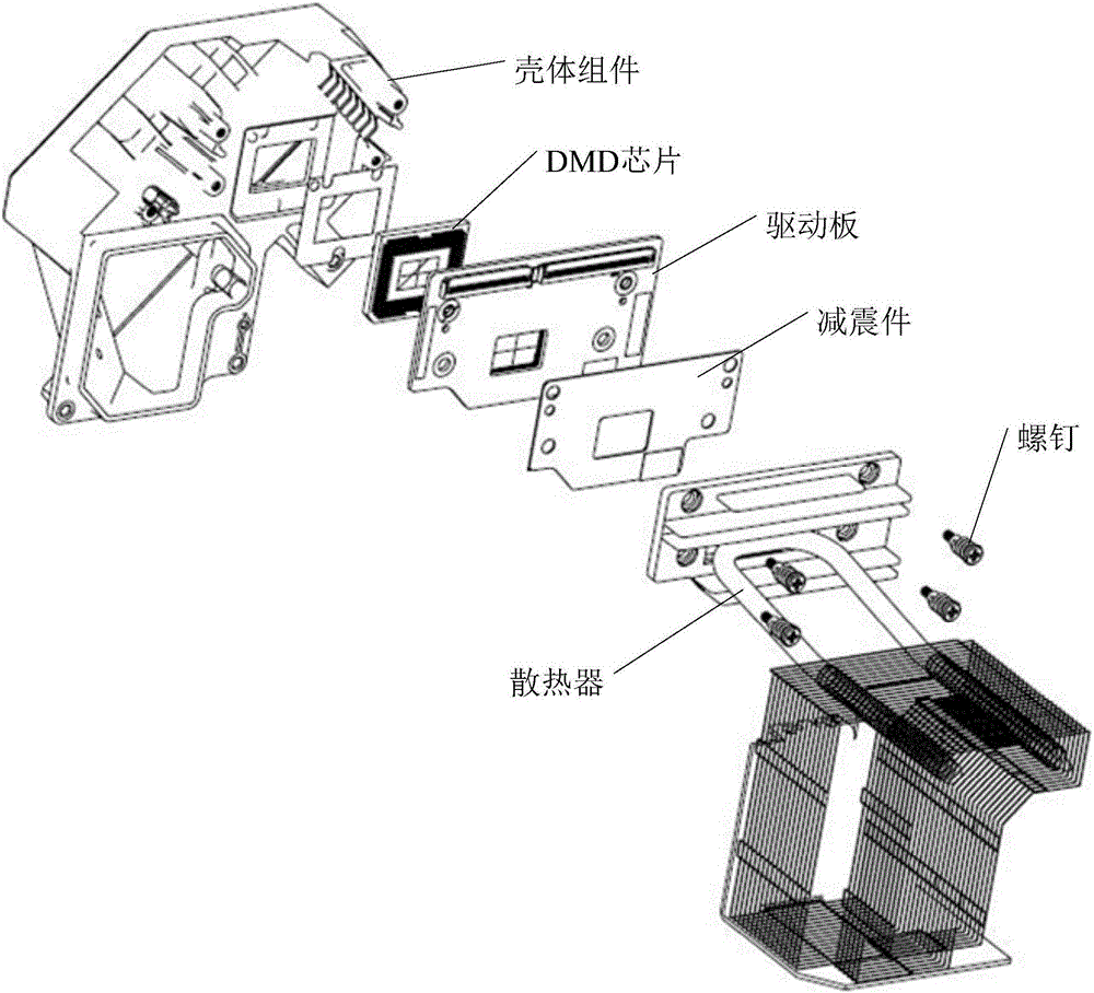
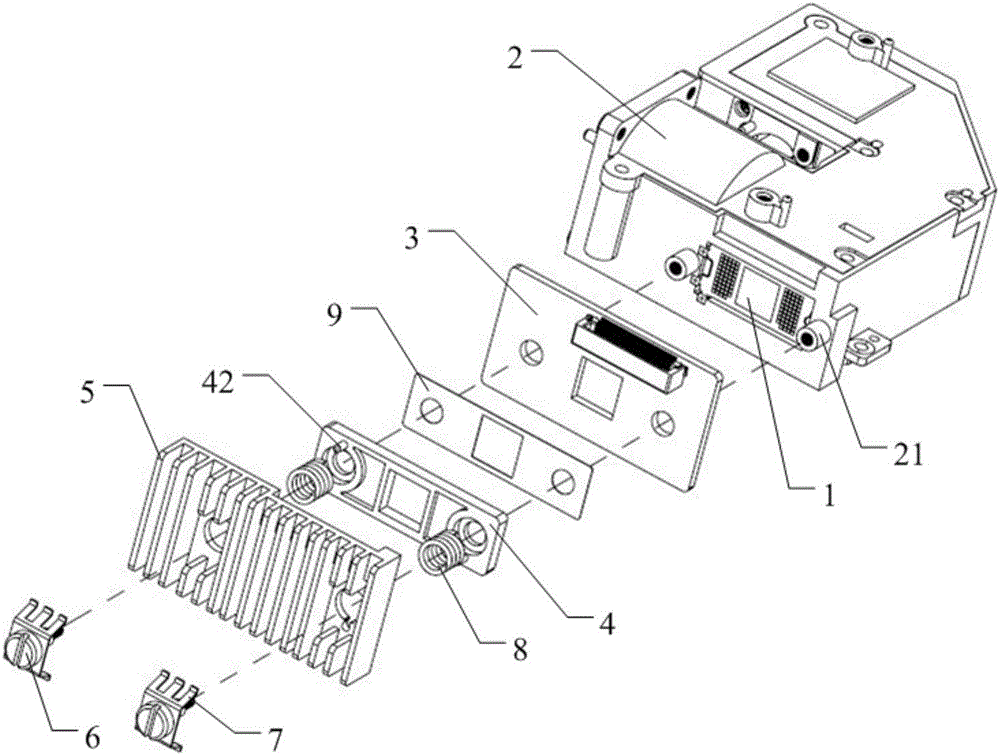
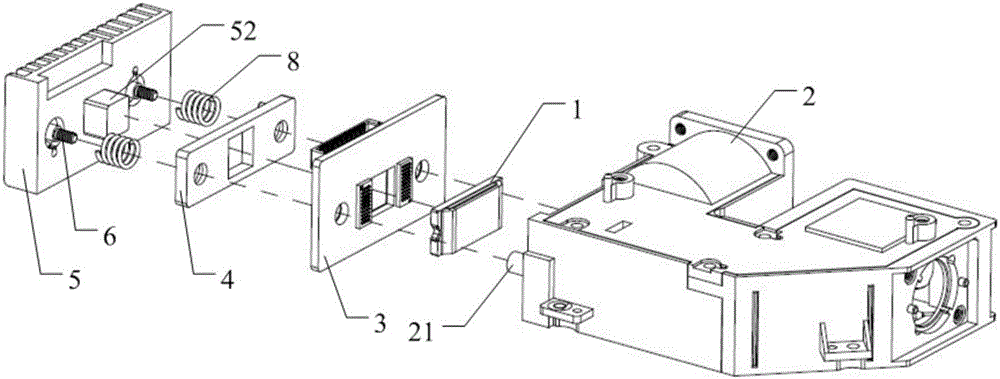
[0032] A schematic structural view of a typical embodiment of a DMD assembly provided by the present invention is shown in 2 to 4. The DMD assembly includes a DMD chip 1, a main housing 2, a drive board 3, a fixing piece 4, a heat sink 5 and screws 6.

[0033] Wherein, the main housing 2 is provided with a placement groove (not marked) for installing and fixing the DMD chip 1, and the main housing 2 is preferably the main housing in the DMD optical-mechanical assembly (or integrally arranged on the DMD optical on the main housing in the machine assembly). The DMD chip 1 and the driver board 3 adopt point-type elec...


PUM


Abstract

The invention relates to the field of optical and projection technology, and more particularly to a DMD module, a DLP machine and a DLP projection device. The DMD module includes a DMD chip, a main housing, a driving plate, a fixing member, a radiator and a connecting member. The radiator includes a radiating block. Through holes are disposed in the fixing member and the driving plate. The DMD chip is fixedly mounted on the main housing, the connecting member is connected to the main housing through the radiator, the fixing member and the driving plate in sequence, and the radiating block is in contact with the back surface of the DMD chip through the through holes in the fixing member and the driving plate. A spring piece is disposed between a stopper portion of the connecting member and the radiator, a spring is disposed between the stopper portion of the connecting member and the fixing member, and the spring passes through the radiator. Therefore, the invention can radiate the heat generated by the DMD chip in time, and ensure the contact accuracy and stability between the DMD chip and the driving plate, thereby improving the quality of a final output image.

Description

[0001] 【Technical field】 [0002] The invention relates to the field of optics and projection technology, in particular to a DMD component, a DLP optical machine and a DLP projection device. [0003] 【Background technique】 [0004] DLP (Digtal Light Processing, digital light processing) projectors have the characteristics of high native contrast, miniaturization of the machine, and closed optical path, making them more and more popular among users. Among them, DLP projectors use DMD ( Digtal Micromirror Device (digital micromirror device) chip is used as an imaging device, a projection technology that realizes projected images by adjusting reflected light. The DMD chip is the core component of the optical-mechanical assembly. In the optical-mechanical assembly, the light beam emitted by the laser passes through a series of optical lenses and finally reaches the DMD chip. The DMD chip processes the optical signal and finally forms an image. [0005] At present, the connection m...

Claims


Application Information

Patent Timeline
Patent Type & Authority Applications(China)
IPC IPC(8): G03B21/16G03B21/00G02B26/08
CPCG03B21/008G02B26/0833G03B21/16
Inventor 田新团杨长明
Owner HISENSE
Why Eureka
Try Eureka