Aeronautical composite material box molding tooling

A composite material and molding tooling technology, which is applied in the field of composite material part structure molding, can solve problems such as increased labor costs, difficulty in demoulding parts, and unsatisfactory effects, and achieves the goals of reducing labor costs, convenient demoulding, and avoiding scrapping Effect

Inactive Publication Date: 2015-12-23
FESHER AVIATION COMPONENTS ZHENJIANG
View PDF3 Cites 0 Cited by
  • Summary
  • Abstract
  • Description
  • Claims
  • Application Information

AI Technical Summary

Problems solved by technology

There are following defects in the above-mentioned forming tooling structure: the first, as attached figure 1 As shown, during the mold clamping and curing process, the resin base will flow along the mold clamping seam 4a, and be consolidated at the fastening bolt connection 5a. Too much resin base solidification makes it difficult to remove the fastening bolt 3a from the tooling. As a result, it is difficult to demould the parts, and even lead to the scrapping of the parts; secondly, even if the fastening bolts 3a are removed during demoulding, the resin base will solidify on the threads and form glue spots, which need to be passed through with tools such as non-metallic wedges and hammers. Cleaning by manual beating is often difficult and the effect is not ideal, which increases the labor cost

Method used


Image

  • Aeronautical composite material box molding tooling
  • Aeronautical composite material box molding tooling
  • Aeronautical composite material box molding tooling

Examples


Embodiment 1

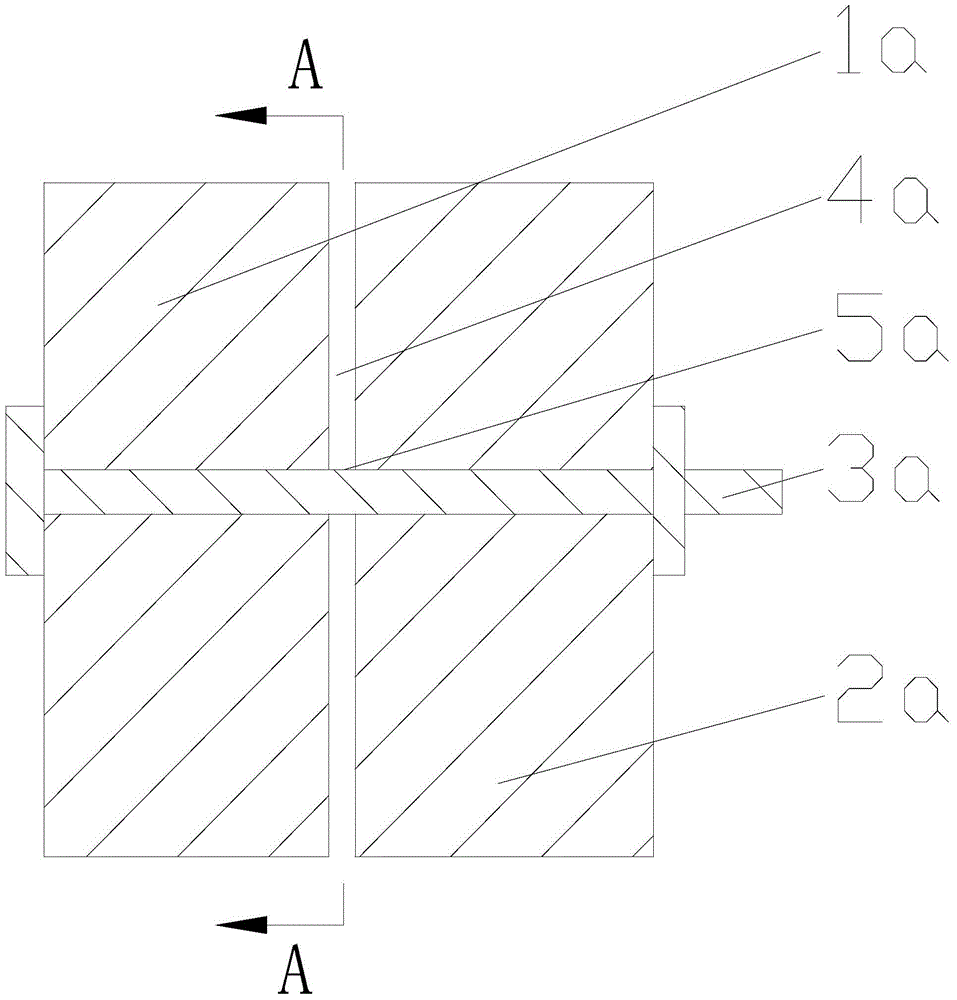
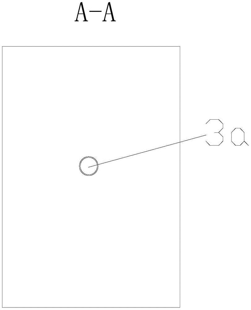
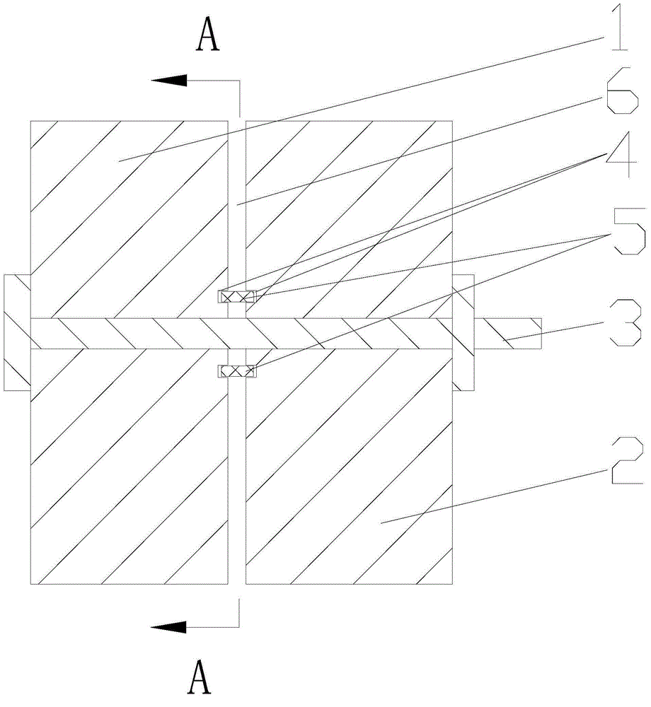
[0016] as attached Figure 3-4 As shown, an aviation composite material box forming tooling includes a left mold 1, a right mold 2 and fastening bolts 3, and the left mold 1 and the right mold 2 are connected by the fastening bolts 3 to be clamped and fixed. On the clamping surfaces of the left mold 1 and the right mold 2, grooves 4 are respectively provided at the joints of the fastening bolts 3, and the positions of the grooves 4 correspond to each other and have the same shape, corresponding to the cavity formed by the groove 4 after mold closing. A detachable silicone rubber ring 5 is placed, the shape of the silicone rubber ring 5 is consistent with the shape of the groove 4, and the size of the groove cavity is slightly larger than the size of the silicone rubber ring 5, as attached Figure 4 As shown, the groove 4 is circular, and the corresponding silicone rubber ring 5 is also circular. The silicone rubber ring 5 has excellent high temperature resistance and sealing ...

Embodiment 2

[0018] This embodiment is basically the same as Embodiment 1, except that the shape of the groove 4 is elliptical, and the corresponding silicone rubber ring 5 is elliptical in the same shape as the groove 4 .

Embodiment 3

[0020] This embodiment is basically the same as Embodiment 1, except that the groove 4 is rectangular in shape, and the corresponding silicone rubber ring 5 is rectangular in the same shape as the groove 4 .


PUM


Abstract

The invention discloses an aeronautical composite material box molding tooling, which includes a left die, a right die and a fastening bolt. The left die and the right die are connected by the fastening bolt to achieve die clamping and fixation. The die clamping surface of the left die and the right die is provided with grooves with corresponding positions and consistent shape at the fastening bolt joints respectively. A detachable silicon rubber ring is placed in the groove cavity formed after die clamping of the corresponding grooves, and the size of the groove cavity is slightly larger than the size of the silicon rubber ring. The grooves can be in the shape of a circle, oval, rectangle, square or any one of other closed figures. The silicon rubber ring and the grooves have a consistent shape. According to the invention, during curing, the silicon rubber ring effectively blocks overspill of the composite material's resin matrix, thus avoiding consolidation of the composite material's resin matrix at the fastening bolt joints. The molded parts can realize convenient demolding, thus avoiding scrapping. The fastening bolt and the silicon rubber ring are easy to clean, the labor cost is reduced, the production efficiency is enhanced, and the quality of subsequent products is ensured.

Description

technical field [0001] The invention relates to the technical field of structural forming of composite material parts, in particular to an aviation composite material box forming tooling. Background technique [0002] Composite materials, metal materials, inorganic non-metal materials, and polymer materials are listed as four major material systems. Advanced composite materials refer to the composite materials used to process the main load-bearing structure and secondary load-bearing structure, whose stiffness and strength properties are equivalent to or exceed aluminum alloys, and have light weight, high specific strength, specific modulus, and better Ductility, corrosion resistance, heat insulation, sound insulation, shock absorption, high (low) temperature resistance, etc. [0003] Advanced composite materials such as resin-based fiber-reinforced composite materials have been widely used in the aerospace industry. The structure of the existing aviation resin-based compos...

Claims


Application Information

Patent Timeline
Patent Type & Authority Applications(China)
IPC IPC(8): B29C70/54B29C33/00
CPCB29C70/54B29C33/0038
Inventor 何国亮魏春哲赵会民
Owner FESHER AVIATION COMPONENTS ZHENJIANG
Why Eureka
Try Eureka