Wear-resistant steel ball quenching equipment

A technology of quenching equipment and wear-resistant steel, which is applied in the direction of quenching equipment, heat treatment equipment, furnaces, etc., and can solve the problems of affecting the quality of quenching liquid, temperature transfer and distribution, affecting the quenching effect of wear-resistant steel balls, and failing to achieve the quenching effect, etc. , to achieve the effect of fast heat transfer speed, quenching speed and easy hardening, fast quenching speed

Inactive Publication Date: 2015-12-23
NINGGUO SOUTHERN WEAR RESISTANT MATERIALS
View PDF4 Cites 0 Cited by
  • Summary
  • Abstract
  • Description
  • Claims
  • Application Information

AI Technical Summary

Problems solved by technology

[0002] Wear-resistant steel balls need to be quenched and tempered at a certain temperature to improve their strength, hardness, wear resistance, fatigue strength and toughness. The quenching effect has a great influence. If the temperature of the quenching liquid is too high, the cooling rate will drop significantly, and the quenching effect will not be achieved. It is very necessary to use cooling equipment to cool the quenching liquid.
[0003] After quenching, the impurities on the surface of wear-resistant steel balls will be mixed into the quenching liquid. The large particles will sink to the bottom of the quenching pool under the action of gravity, and the small particles will float or suspend in the quenching liquid under the action of buoyancy, affecting the quenching liquid. The quality and temperature transfer and distribution of the material will affect the quenching effect of the next batch of wear-resistant steel balls

Method used


Image

  • Wear-resistant steel ball quenching equipment
  • Wear-resistant steel ball quenching equipment

Examples


Embodiment Construction

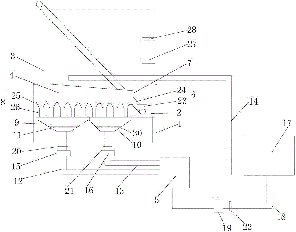
[0025] Such as figure 1 as shown, figure 1 It is a structural schematic diagram of a kind of wear-resistant steel ball quenching equipment proposed by the present invention; figure 2 It is a schematic plan view of the transmission device in a wear-resistant steel ball quenching equipment proposed by the present invention.

[0026] refer to figure 1 , figure 2 , a wear-resistant Steel ball quenching equipment , including a frame 1, a quenching pool 2, a first tube 3, a second tube 4, a cooling box 5, and a delivery device 6;

[0027] The quenching pool 2 is arranged on the frame 1 .

[0028] The first end of the first ball losing pipe 3 is arranged on the outside above the quenching pool 2, and the second end is connected with the first end of the second ball losing pipe 4, and the second ball losing tube 4 is arranged at the bottom of the quenching pool 2, and the second ball losing tube 4 is arranged on the bottom of the quenching pool 2. The second end of the tube 4...


PUM


Abstract

The invention proposes wear-resistant steel ball quenching equipment. The wear-resistant steel ball quenching equipment comprises a quenching pool, a first ball conveying pipe, a second ball conveying pipe, a cooling box and a conveying device, wherein a first end of the first ball conveying pipe is arranged at the outer side of the upper side of the quenching pool, and a second end is connected with a first end of the second ball conveying pipe; the second ball conveying pipe is arranged at the bottom of the quenching pool; a steel ball outlet is formed in a second end of the second ball conveying pipe; multiple dust outlet pipes are arranged at the lower part of the second ball conveying pipe along a steel ball output direction in sequence, and penetrate through the bottom of the quenching pool; the dust outlet pipes at the front section and the back section of the second ball conveying pipe are respectively communicated with a first liquid colleting part and a second liquid collecting part; a first filter and a second filter are respectively arranged in the first liquid collecting part and the second liquid collecting part; the first liquid collecting part and the second liquid collecting part are respectively communicated with the cooling box; the cooling box is communicated with the quenching pool; and one end of the conveying device is arranged below the steel ball outlet, and the other end is arranged at the outer side of the upper side of the quenching pool. The wear-resistant steel ball quenching equipment is uniform in quenching, easy for through hardening and fast in speed, obviously improves the quenching effect, and promotes the quenching efficiency.

Description

technical field [0001] The invention relates to the technical field of wear-resistant steel ball processing, in particular to a wear-resistant steel ball quenching equipment. Background technique [0002] Wear-resistant steel balls need to be quenched and tempered at a certain temperature to improve their strength, hardness, wear resistance, fatigue strength and toughness. The quenching effect has a great influence. If the temperature of the quenching liquid is too high, the cooling rate will decrease significantly, and the quenching effect will not be achieved. It is very necessary to use cooling equipment to cool the quenching liquid. [0003] After quenching, the impurities on the surface of wear-resistant steel balls will be mixed into the quenching liquid. The large particles will sink to the bottom of the quenching pool under the action of gravity, and the small particles will float or suspend in the quenching liquid under the action of buoyancy, affecting the quenchin...

Claims


Application Information

Patent Timeline
Patent Type & Authority Applications(China)
IPC IPC(8): C21D1/64C21D9/36
Inventor 熊夏鸣
Owner NINGGUO SOUTHERN WEAR RESISTANT MATERIALS
Why Eureka
Try Eureka