Supercharge Your Innovation With Domain-Expert AI Agents!

A Structural System of Field Beam Column Cap and Beamless Floor Slab

A beam-column and system technology, applied in the field of field beam-column cap and beamless floor structure system, can solve the problem that the column cap and the lattice column cannot be effectively connected, the deformation of the enclosure structure is increased, and the over-excavation depth is increased. problems, to achieve the effect of reasonable stress, reasonable structural stress and reduction of over-excavation depth

Active Publication Date: 2017-10-13
NO 2 CONSTR GRP CO LTD OF SHANGHAI CONSTR GRP
View PDF6 Cites 0 Cited by
  • Summary
  • Abstract
  • Description
  • Claims
  • Application Information

AI Technical Summary

Problems solved by technology

The column caps in the traditional slab-column system are large, thick, and heavy, which affects the appearance and is inconvenient for construction
Especially in the upside-down method, the construction is particularly inconvenient. The column cap and the lattice column cannot be effectively connected, and the over-excavation depth of each floor increases, which increases the deformation of the enclosure structure

Method used


Image

  • A Structural System of Field Beam Column Cap and Beamless Floor Slab
  • A Structural System of Field Beam Column Cap and Beamless Floor Slab
  • A Structural System of Field Beam Column Cap and Beamless Floor Slab

Examples


Embodiment 1

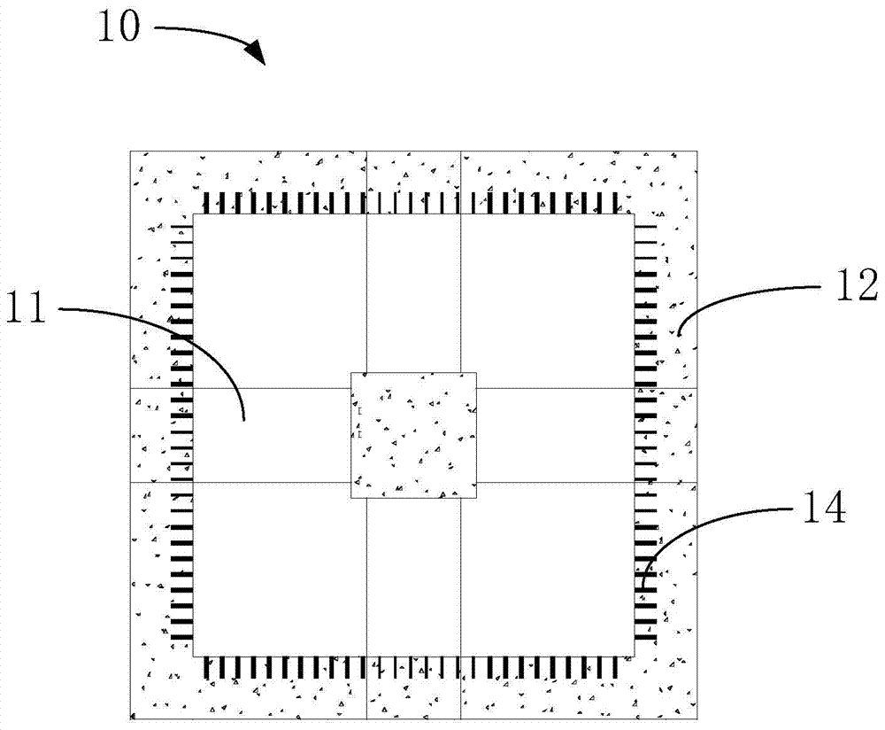
[0030] The cross-shaped beam column cap provided by the invention, such as figure 1 and figure 2 As shown, it is applied to the construction of the straight method, including the cross beam 11 and the cross beam 11 peripheral mouth ring beam 12, and the four ends of the cross beam 11 are respectively connected to the middle of each side of the mouth ring beam 12. Points are just connected to form a cross-shaped beam. Specifically, the cross-shaped beam is bound with steel bars. Please combine Figure 5 , the upper surface of the cross beam 11 is flush with the upper surface of the structural plate 20, the mouth circle beam 12 is located at the bottom of the structural plate 20, and the lower surface of the cross beam 11 is flush with the mouth circle The lower surface of the beam 12 is flush. The present invention effectively connects the cross beam 11 with the concrete column, effectively combines the structural plate 20 with the structural floor slab poured in the cross b...

Embodiment 2

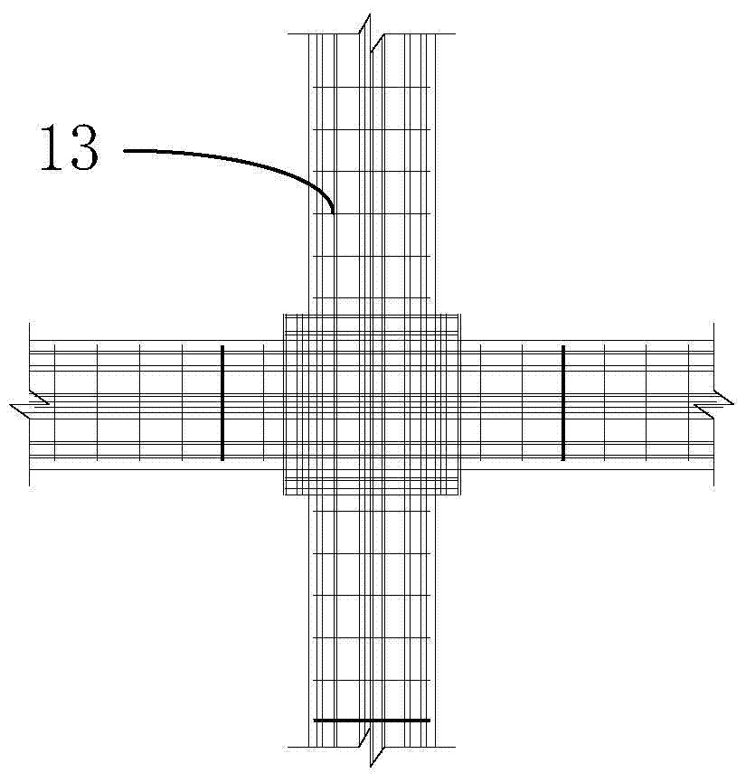
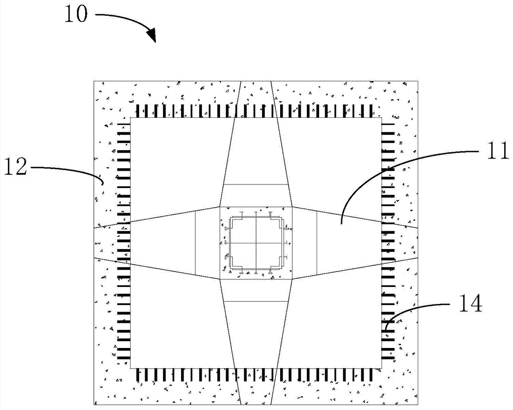
[0035] The difference between this embodiment and Embodiment 1 is: Please refer to image 3 and combine Figure 5 , the cross-shaped beam column cap 10 in this embodiment is applied in the reverse construction method, and the cross beam 11 is gradually reduced in width from the intersection point. The distribution of rib 13 is as follows Figure 4 As shown, a beam system is formed at the top of the lattice column 30, so that the checking calculation of the punching shear is converted into the checking calculation of the shear bearing capacity, and the rationality of the force is increased; in addition, for the basement constructed by the reverse construction method, the The over-excavation depth at each floor of the foundation pit reduces the deformation of the enclosure structure and improves the progress of the beamless floor in the reverse construction method.

[0036] Preferably, please continue to refer to Figure 5 , the cross beam 11 is provided with a corbel support...


PUM


Abstract

The invention relates to a structural system of a cross-beam column cap and a beamless floor slab. The cross-beam column cap includes a cross beam and a circle beam around the cross beam. The four ends of the cross beam are respectively connected to the cross beam. The midpoints of each side of the cross beam are just connected, the upper surface of the cross beam is flush with the upper surface of the structural plate, the cross beam is arranged at the bottom of the structural plate, and the lower surface of the cross beam is The surface is flush with the lower surface of the word circle beam. The invention effectively connects the cross beam with the concrete column or the lattice column, effectively combines the structural plate with the structural floor poured in the column cap of the field beam through the outer circle beam, and improves the punching resistance of the joint of the column cap of the field beam. The force is converted into shear force, the force is more reasonable, and the space occupied by the Tianzi beam column cap is small and more beautiful.

Description

technical field [0001] The invention relates to the field of concrete structure systems, in particular to a field beam column cap and beamless floor structure system. Background technique [0002] The existing basement floor structures mainly include beam-slab system and beamless system. [0003] Among them, the calculation software of the beam-slab system has a high degree of simulation. Most of the building structure floors adopt the beam-slab system. This structural system has clear vertical force, clear force transmission path, good seismic performance, and flexible opening and lifting of the floor. , save the amount of steel and concrete. However, the beam-slab system reduces the indoor net height and reduces the use space; increases the column, wall height, excavation depth, and the length of some equipment and pipelines, which increases the construction cost; the amount of formwork used during construction is large, and the formwork construction efficiency is high. ...

Claims


Application Information

Patent Timeline
Patent Type & Authority Patents(China)
IPC IPC(8): E02D29/045
Inventor 龙莉波马跃强李成
Owner NO 2 CONSTR GRP CO LTD OF SHANGHAI CONSTR GRP
Features
  • R&D
  • Intellectual Property
  • Life Sciences
  • Materials
  • Tech Scout
  • Unparalleled Data Quality
  • Higher Quality Content
  • 60% Fewer Hallucinations
Learn More