Pulse width modulation switching-on method and system of LED display driving

A technology of pulse width modulation and display drive, which is applied to static indicators, instruments, etc., and can solve problems such as small brightness unevenness, electromagnetic interference, and LED current instability in LED display systems

Active Publication Date: 2015-12-23
SUPEC SUZHOU
View PDF5 Cites 3 Cited by
  • Summary
  • Abstract
  • Description
  • Claims
  • Application Information

AI Technical Summary

Problems solved by technology

[0003] figure 2 It shows the output timing diagram of the actual pulse width modulation PWM, Y[m] is the output voltage of m rows, OUT[n] is the current source waveform of n columns, the PWM synchronous control is the PWM synchronous control signal, td1 is the column output waiting time, t ON is the conduction time of the LED in the PWM cycle, t OFF is the turn-off time of the LED in the PWM cycle, and td2 is the row turn-off waiting time; the defect of the existing PWM mode is that, affected by the rising speed of the row voltage source, Y[m] output to the working voltage requires a certain Rise time, this rise time will be affected by the number of column current sources, when the column current is more, the rise rate of Y[m] will be slower, tr is the rise time of Y[m], td1 is the column waiting output time, When tr>td1, ts=tr-td1, within ts, affected by the voltage of Y[m], the voltage difference between Y[m] and OUT[n] is unstable during ts, which leads to flow The current through the LED is unstable, which will lead to the problem of uneven brightness of the LED display system; the output points of the existing column current sources all start at point B, which will further increase the time of tr; at point A , because the column current sources are turned on at the same time, resulting in the maximum instantaneous current, which will generate strong electromagnetic interference EMI

Method used


Image

  • Pulse width modulation switching-on method and system of LED display driving
  • Pulse width modulation switching-on method and system of LED display driving
  • Pulse width modulation switching-on method and system of LED display driving

Examples


Embodiment 1

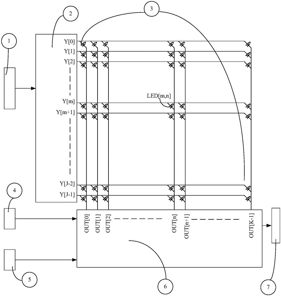
[0055] The present invention also provides a pulse width modulation conduction system for LED display drive. Embodiment 1 of the system of the present invention specifically includes:

[0056] PWM period register, PWM brightness register, subtractor, bias bit register, shifter, adder and conduction module;

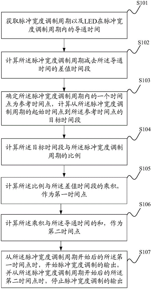
[0057] The PWM period register is used to obtain the pulse width modulation period;

[0058] The PWM brightness register is used to obtain the conduction time of the LED in the pulse width modulation cycle;

[0059] The subtractor is used to calculate the difference time period of the pulse width modulation period minus the conduction time;

[0060] The subtractor is used to determine a time point in the pulse width modulation cycle as a reference time point, calculate a target time period from the start time point of the pulse width modulation cycle to the reference time point, and calculate the the ratio of the target time period to the pulse width modulation period; ...


PUM


Abstract

The invention discloses a pulse width modulation switching-on method and system of LED display driving. The method includes the following steps that: a pulse width modulation period tPMW and the switching-on time tON of an LED in the tPMW are obtained; a difference value time period which is obtained through subtracting tON from tPMW can be obtained; a time point in tPMW is determined as a reference time point, and a target time period from a starting time point to the reference time point of tPMW is calculated; and the ratio x of the target time period to tPMW is calculated; the product of x and the difference value time period is adopted as a first time point; the sum of the product and the switching-on time is adopted as a second time points; after tPMW begins, the output of pulse width modulation is initiated at the first time point, and the output of pulse width modulation is stopped at the second time point; a time period length value from the first time point to the reference time point is equal to the product value of the switching-on time and the ratio, and line output voltage is stabilized before PWM switching on, and therefore, the voltage difference of the line output voltage and column current is stable in the PWM switching-on time, and current flowing through the LED is stable.

Description

technical field [0001] The invention relates to the technical field of LED display, in particular to a pulse width modulation conduction method and system for LED display driving. Background technique [0002] figure 1 Shows the structure of the dynamic LED display, including: row address bus 1, row voltage source 2, LED display matrix 3, luminance input clock (GCLK) 4, data input bus 5, column current source 6, data output bus 7. A display matrix with J rows and K columns is formed. This matrix is ​​called LED[J, K], and the LEDs with m rows and n columns are identified as LED[m, n]. [0003] figure 2 It shows the output timing diagram of the actual pulse width modulation PWM, Y[m] is the output voltage of m rows, OUT[n] is the current source waveform of n columns, the PWM synchronous control is the PWM synchronous control signal, td1 is the column output waiting time, t ON is the conduction time of the LED in the PWM cycle, t OFF is the turn-off time of the LED in th...

Claims


Application Information

Patent Timeline
Patent Type & Authority Applications(China)
IPC IPC(8): G09G3/32
Inventor 范立新
Owner SUPEC SUZHOU
Why Eureka
Try Eureka