
Energy saving reactive compensation cabinet based on intelligent capacitor

A technology of smart capacitors and compensation cabinets, applied in reactive power compensation, reactive power adjustment/elimination/compensation, etc., can solve the problem that the loads of each phase cannot achieve a good compensation effect, cannot meet the performance requirements of capacitor compensation cabinets, and resist inrush currents Problems such as poor overload capacity, to achieve the effects of no arcing phenomenon, improved service life, and improved overall performance

Pending Publication Date: 2015-12-23
NINGBO CHEN LAN ELECTRIC EQUIP
View PDF1 Cites 0 Cited by
  • Summary
  • Abstract
  • Description
  • Claims
  • Application Information

AI Technical Summary

Problems solved by technology

[0003] In the existing technology, because the user load uses more frequency converters, the switching switch used in the capacitor compensation cabinet is a composite switch, which has disadvantages such as poor voltage withstand capability, poor anti-surge overload capability, and easy damage. Most of the compensation methods use three-phase simultaneous compensation, which cannot achieve a good compensation effect on the loads of each phase
Moreover, the cabinet body of the capacitance compensation cabinet in the prior art is generally made of a single material, which cannot meet the performance requirements required for the operation of the capacitance compensation cabinet, resulting in a short service life

Method used


Image

  • Energy saving reactive compensation cabinet based on intelligent capacitor
  • Energy saving reactive compensation cabinet based on intelligent capacitor
  • Energy saving reactive compensation cabinet based on intelligent capacitor

Examples


Embodiment 1

[0060] Mix epoxy resin, flow modifier, heat-resistant modifier, compatibilizer, primary antioxidant, auxiliary antioxidant, and processing aid in a high-speed mixer in the following percentages by weight: bisphenol A epoxy 55wt% resin; 2wt% flow modifier; 2wt% heat-resistant modifier; 3.2wt% compatibilizer; 0.4wt% primary antioxidant; 0.4wt% auxiliary antioxidant; The flow modifier is maleic anhydride grafted acrylate and styrene copolymer; the heat-resistant modifier is N,N'-(4,4'-methylenediphenyl)bis One or both of maleimide and maleic anhydride grafted polystyrene; the main antioxidant is antioxidant 1076, antioxidant 1098, antioxidant 1010, antioxidant 2246, One or more of the antioxidant 4010 or the antioxidant DNP; the auxiliary antioxidant is one or both of the antioxidant 168 or the antioxidant 626.

[0061] The mixed raw materials are melted by a twin-screw extruder, and at the same time, 20wt% of alkali-free glass fiber and 15wt% of carbon fiber after surface oxida...

Embodiment 2

[0063] Epoxy resin, flow modifier, heat-resistant modifier, compatibilizer, main antioxidant, auxiliary antioxidant, processing aid are mixed at high speed in a high-speed mixer according to the following weight percentage: TDE85 epoxy resin 52wt% ; Flow modifier 4wt%; heat-resistant modifier 2.2wt%; compatibilizer 4wt%; main antioxidant 0.5wt%; auxiliary antioxidant 0.3wt%; The flow modifier is maleic anhydride grafted acrylate and styrene copolymer; the heat-resistant modifier is N,N'-(4,4'-methylenediphenyl)bis One or both of maleimide and maleic anhydride grafted polystyrene; the main antioxidant is antioxidant 1076, antioxidant 1098, antioxidant 1010, antioxidant 2246, One or more of the antioxidant 4010 or the antioxidant DNP; the auxiliary antioxidant is one or both of the antioxidant 168 or the antioxidant 626.

[0064] The mixed raw materials are melted by a twin-screw extruder, and at the same time, 15wt% of alkali-free glass fiber and 20wt% of carbon fiber after su...

Embodiment 3

[0066] Mix epoxy resin, flow modifier, heat-resistant modifier, compatibilizer, primary antioxidant, auxiliary antioxidant, and processing aid in a high-speed mixer in the following percentages by weight: bisphenol A epoxy 60wt% resin; 5wt% flow modifier; 3wt% heat-resistant modifier; 5wt% compatibilizer; 0.5wt% primary antioxidant; 0.5wt% auxiliary antioxidant; The flow modifier is maleic anhydride grafted acrylate and styrene copolymer; the heat-resistant modifier is N,N'-(4,4'-methylenediphenyl)bis One or both of maleimide and maleic anhydride grafted polystyrene; the main antioxidant is antioxidant 1076, antioxidant 1098, antioxidant 1010, antioxidant 2246, One or more of the antioxidant 4010 or the antioxidant DNP; the auxiliary antioxidant is one or both of the antioxidant 168 or the antioxidant 626.

[0067] The mixed raw materials are melted by the twin-screw extruder, and at the same time, 13wt% of alkali-free glass fiber and 10wt% of carbon fiber after surface oxida...


PUM


Abstract

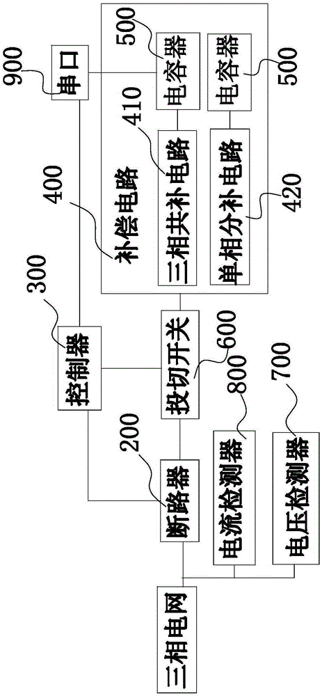
The invention provides an energy saving reactive compensation cabinet based on an intelligent capacitor, belonging to an electric power control device, and comprises a cabinet body, in which a breaker, a controller and a compensating circuit are arranged. The compensating circuit comprises a plurality of sets of three-phase joint compensating circuits and single-phase separate compensating circuits; each three-phase joint compensating circuit and each single-phase separate compensating circuit both comprise a capacitor, and a switching switch used for controlling the capacitor to provide reactive compensation; the breaker is in connection with a three-phase power grid power supply, and is used for controlling power on / off states of a whole reactive compensation cabinet; the controller is in series connection between the breaker and the compensating circuit; the power supply of each phase is provided with a voltage detector and a current detector. The cabinet body is prepared by composite materials of reasonable compatibility, including: 50-60 wt% of epoxy resin, 10-25 wt% of alkali-free glass fibers, 10-25 wt% of carbon fibers, 0.5-5 wt% of flow modifiers, 1-3 wt% of heatproof modifiers, 3-5 wt% of compatilizers, 0.3-0.5 wt% of main anti-oxidants, 0.3-0.5 wt% of auxiliary anti-oxidants, and 1-3 wt% of processing auxiliary agents. The energy saving reactive compensation cabinet has sound compensation effects and a long service life, and is not easy to damage.

Description

Technical field: [0001] The invention relates to a power control device, in particular to an energy-saving reactive power compensation cabinet based on an intelligent capacitor. Background technique: [0002] Most of the electrical loads in the grid, such as motors and transformers, are inductive loads, and corresponding reactive power must be provided to these devices during operation. After installing reactive power compensation equipment such as shunt capacitors in the grid, it can provide reactive power consumed by inductive loads, reducing the reactive power transmitted from grid power to inductive loads and lines, and reducing the reactive power in the grid. Flow, so it can reduce the power loss of lines and transformers caused by the transmission of reactive power. The function of the capacitance compensation cabinet is equivalent to connecting a capacitor in parallel with the electric load. The current of the capacitor will offset a part of the inductor current, the...

Claims


Application Information

Patent Timeline
Patent Type & Authority Applications(China)
IPC IPC(8): H02J3/18
CPCY02E40/30
Inventor 李华元李旭锋任元魁胡成敏
Owner NINGBO CHEN LAN ELECTRIC EQUIP
Learn More