Membrane device and process for mass exchange, separation, and filtration
A kind of equipment, technology in equipment, applied in the direction of separation method, lighting and heating equipment, chemical instrument and method, etc., can solve the problem that the membrane filter is not suitable, etc.
- Summary
- Abstract
- Description
- Claims
- Application Information
AI Technical Summary
Problems solved by technology
Method used
Image
Examples
Embodiment 1
[0120] [filter application]
[0121] use Figure 7A membrane module. A cross-flow membrane module is constructed and configured for filtering and harvesting algae. In Table 1 the design parameters for the membrane modules are listed.
[0122] Table 1 lists the dimensions and components of a typical cross-flow membrane module for filtration applications.
[0123] Diaphragm scale
[0124] width
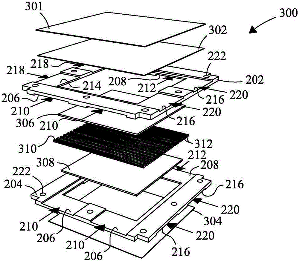
[0125] as reference Figure 4B As described, capsules are stacked on top of each other. Corrugated (wavy) nickel (Ni) mesh was placed between the individual bellows in the stack, and between bellows positioned adjacent the top and bottom cover plates. The membrane module consists of 9 membrane cassettes with 10 feed tanks and 9 permeate tanks. The wavy Ni mesh was used as spacer material and to support the membrane in the bellows during recoil. During normal filtration operation, the pressure on the feed side of the membrane device is greater than the pressure...
Embodiment 2
[0127] [Membrane module for dehumidification]
[0128] use Figure 7A membrane module. Cross-flow membrane modules are constructed and configured for molecular separation and dehumidification. In Table 2 the design parameters for the membrane modules are listed.
[0129] Table 2 lists the dimensions and components of a typical cross-flow membrane module for air dehumidification applications.
[0130] Dimensions of diaphragm used
width
5.25cm
length
11.25cm
Diaphragms exposed to moist air
width
4cm
length
10cm
Number of diaphragms
6
Number of bellows
3
channel height
0.1cm
Supply channel spacing
4cm
Number of supply slots
4
Permeate side
Polyester base (0.5mm) thickness
0.1cm
open access height
0.1cm
Number of infiltration tanks
3
Calculation results
...
Embodiment 3
[0144] [Membrane modules for humidity exchange and heat exchange]
[0145] A counterflow membrane module was fabricated with a single 50 μm thick zeolite / Ni membrane configured with a 4 cm x 10 cm active area and subjected to air dehumidification and enthalpy exchange measurements. The module has a symmetrical design. The same base material was placed on both sides of the membrane. A 0.5 mm thick sheet of fabric polyester was placed on the rear side of the diaphragm. A 0.5 mm thick sheet of fabric polyester was placed between the diaphragm and cover plate. The feed gas flow is introduced from one side of the membrane. Sweep gas flow is introduced from the other side of the diaphragm. The feed gas flow through the three inlet ports was distributed over a 10 cm wide membrane. The flow of feed gas flows through the membrane in the opposite direction to the flow of sweep gas. The length of the flow path is 4 cm. Humidity exchange was performed at room temperature with const...
PUM
 Abstract
Description
Claims
Application Information
 - R&D
- Intellectual Property
- Life Sciences
- Materials
- Tech Scout
- Unparalleled Data Quality
- Higher Quality Content
- 60% Fewer Hallucinations
Browse by: Latest US Patents, China's latest patents, Technical Efficacy Thesaurus, Application Domain, Technology Topic, Popular Technical Reports.
© 2025 PatSnap. All rights reserved.Legal|Privacy policy|Modern Slavery Act Transparency Statement|Sitemap|About US| Contact US: help@patsnap.com


