Exhaust gas discharge system for cyanide plating tank

A waste gas discharge system and cyanide technology, applied in chemical instruments and methods, dispersed particle filtration, combined devices, etc., can solve problems such as cyanide-containing electroplating waste gas pollution, and achieve the effects of solving pollution problems, reducing operating costs, and reducing evaporation

Inactive Publication Date: 2015-12-30
嘉兴通惠环保科技有限公司
View PDF6 Cites 0 Cited by
  • Summary
  • Abstract
  • Description
  • Claims
  • Application Information

AI Technical Summary

Problems solved by technology

[0005] The present invention aims at the deficiencies of the above-mentioned prior art, and proposes a cyanide plating tank exhaust gas discharge system, which fundamentally solves the environmental pollution problem of cyanide-containing electroplating exhaust gas, reduces the evaporation of solution in the tank during the process, and has high treatment efficiency , recycle the mixed liquid, reduce operating costs

Method used


Image

  • Exhaust gas discharge system for cyanide plating tank

Examples


Embodiment 1

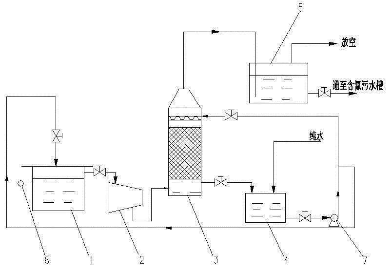
[0016] Embodiment 1: A kind of exhaust gas discharge system of cyanide plating tank.

[0017] Such as figure 1 As shown, the system includes a cyanide plating tank 1, a fan 2, a cyanide mist recovery tower 3, a recovery tank 4 and a reprocessing tank 5; the side of the cyanide plating tank 1 is provided with a gas-collecting outlet at 12 cm below the notch; the cyanide mist recovery A filter layer is provided in the middle of tower 3, a gas outlet is provided at the top, and a liquid outlet is provided at the bottom. The gas-gathering outlet on the side of the cyanide plating tank 1 is connected to the lower part of the cyanide mist recovery tower 3 through the gas-gathering pipeline, and the fan 2 is arranged on the gas-gathering pipeline; the gas outlet at the top of the cyanide mist recovery tower 3 is connected to the reprocessing tank 5 through the gas pipeline The bottom of the cyanide mist recovery tower 3 is connected to the recovery tank 4 through the recovery pipel...

Embodiment 2

[0018] Embodiment 2: Another exhaust gas discharge system for a cyanide plating tank.

[0019] There is a gas-collecting outlet on the side 15cm below the notch of the cyanide plating tank. All the other are identical with embodiment 1.

Embodiment 3

[0020] Embodiment 3: Yet another exhaust gas discharge system for a cyanide plating tank.

[0021] There is a gas-collecting outlet on the side 10cm below the notch of the cyanide plating tank. All the other are identical with embodiment 1.


PUM


Abstract

The invention relates to an exhaust gas discharge system for a cyanide plating tank. The exhaust gas discharge system comprises the cyanide plating tank, a fan, a cyanogen mist recovery tower, a recovery tank and a retreatment tank, wherein a collected gas outlet is formed in the side surface 10-15 cm below the tank opening of the cyanide plating tank; a filtering layer is arranged in the middle of the cyanogen mist recovery tower; the cyanide plating tank, the fan, the cyanogen mist recovery tower and the recovery tank form a recycling and circulating system through a gas collection pipeline, a recovery pipeline, a return pipeline and a reuse pipeline. According to the invention, the collected gas outlet is formed in the side surface of the cyanide plating tank, and an air hood is formed above a liquid level, so that exhaust gas collection is complete, and no cyanogens mist drainage is realized; through a specific retreatment process, the exhaust gas is purified and then discharged, so that recycling is complete, and no pollution to the environment is realized; a pollution-free environment-friendly cyanide-containing electroplating process without exhaust gas discharge is created. In a process, cyanide-containing solution evaporation is reduced, the treatment efficiency is high, and the running cost is reduced through recycling of a cyanide-containing solution; the problem of pollution of the cyanide-containing electroplating exhaust gas to the environment is solved radically.

Description

technical field [0001] The invention belongs to the technical field of electroplating waste gas treatment, in particular to a cyanide plating tank waste gas discharge system. Background technique [0002] plating (Electroplating) is the use of electrolysis Principle The process of plating a thin layer of other metals or alloys on the surface of metal or other material parts, through electroplating, a layer of metal film can be attached to the surface of metal or other material parts, so as to prevent metal oxidation (such as rust) ), improve wear resistance, Conductivity , reflective, anti-corrosion and aesthetic enhancement. Therefore, the electroplating process is widely used in the production process of machinery, hardware and electrical appliances. Electroplating is an indispensable industry for the development of the national economy. The pollution caused by electroplating to the environment cannot be ignored, and the treatment of the three wastes of electroplatin...

Claims


Application Information

Patent Timeline
IPC IPC(8): C25D21/04B01D50/00B01D46/10B01D46/30
Inventor 周健杨关义
Owner 嘉兴通惠环保科技有限公司
Why Eureka
Try Eureka