
Manufacturing method of optimized backside illuminated CIS pixel area deep P-type isolated well

An isolated well and back-illuminated technology, applied in the field of image sensor devices, can solve problems affecting process stability and product yield, island photoresist collapse, and inability to meet mass production process requirements, etc., to overcome ultra-high depth and width Compared with photoresist collapse, the effect of stabilizing the mass production process and improving processability

Inactive Publication Date: 2015-12-30
SHANGHAI HUALI MICROELECTRONICS CORP
View PDF3 Cites 5 Cited by
  • Summary
  • Abstract
  • Description
  • Claims
  • Application Information

AI Technical Summary

Problems solved by technology

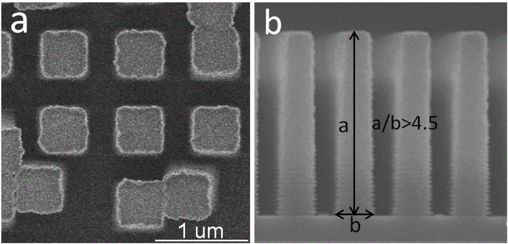
figure 2 The electronic scanning diagram of the photoresist in the photolithography process of the deep P-type isolation well of the CIS product with a pixel unit size of 0.9um and the cross-sectional photo of the photoresist, figure 2 The aspect ratio (a / b) of the photoresist in the photoresist is greater than 4.5, which has significantly exceeded the aspect ratio requirement of a reasonable photolithography process of 3.0. Therefore, the island-shaped photoresist is prone to collapse during the development process, which seriously affects the stability of the process. Sex and product yield, unable to meet mass production process requirements

Method used


Image

  • Manufacturing method of optimized backside illuminated CIS pixel area deep P-type isolated well
  • Manufacturing method of optimized backside illuminated CIS pixel area deep P-type isolated well
  • Manufacturing method of optimized backside illuminated CIS pixel area deep P-type isolated well

Examples


Embodiment Construction

[0025] Below in conjunction with each embodiment, the technical solution of the present invention is clearly and completely set forth, but described embodiment is only the embodiment that the present invention is used for describing description and not all embodiments, based on these embodiments, this invention The solutions obtained by those skilled in the art without creative work all belong to the protection scope of the present invention.

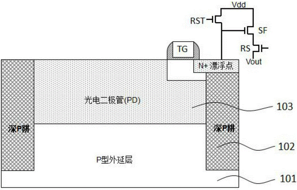
[0026] see figure 1 , showing a schematic diagram of a back-illuminated (Back-illuminated) image sensor back-end 4T pixel unit, the present invention will use this structure to explain the subsequent method. The core idea of ​​the present invention is to disclose a method for forming an optimized deep P-type isolation well in the back-illuminated CIS pixel area. An extended P-type isolation well is formed by the ion implantation process, and a required deep P-type isolation well is jointly formed by using a bidirectional ion implantati...


PUM

PropertyMeasurementUnit
Physical thicknessaaaaaaaaaa
Doping concentrationaaaaaaaaaa
Physical thicknessaaaaaaaaaa

Abstract

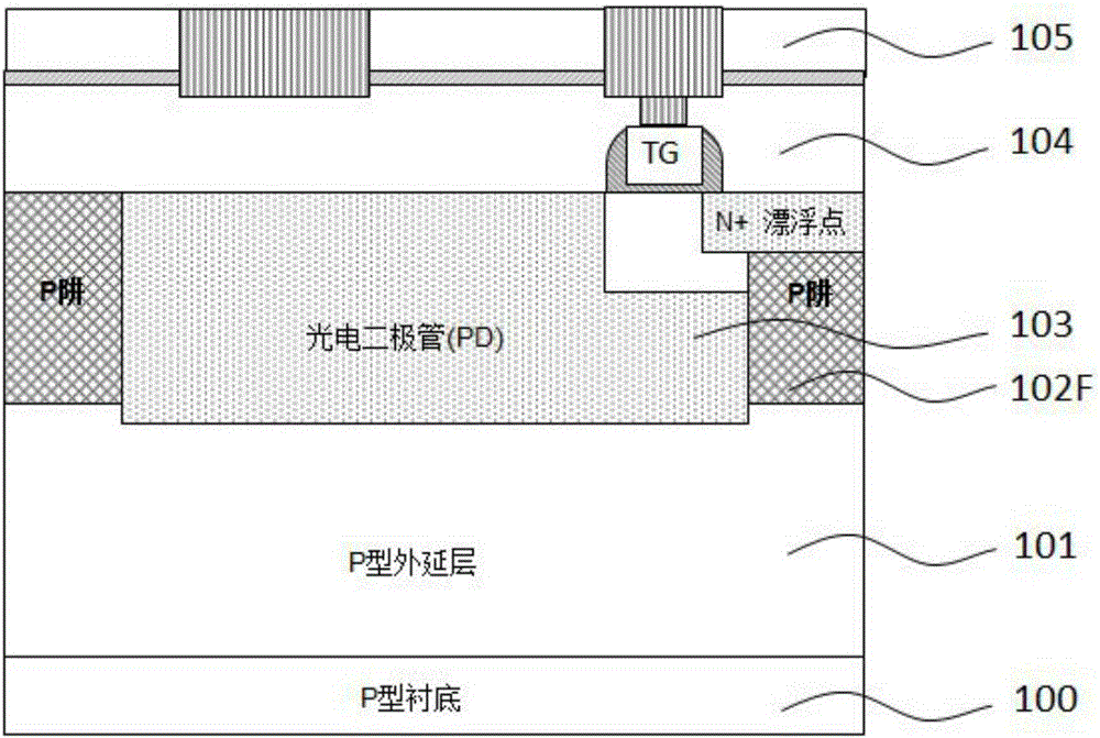
The invention mainly relates to an image sensor device in the field of semiconductors and aims at providing a manufacturing method of an optimized backside illuminated CIS pixel area deep P-type isolated well. Firstly, a first deep P-type isolated well is formed on the front side of a wafer, then a second deep P-type isolated well is formed on the back side of the wafer, and the first deep P-type isolated well and the second deep P-type isolated well are combined to form a whole deep P-type isolated well. The requirements for the depth-to-width ratio of a photoresist and ion beam implantation energy in the forming process of the deep P-type isolated well are effectively reduced, the shortcoming that the ultrahigh depth-to-width ratio existing in the process of a traditional deep P-type isolated well forming process causes photoresist collapse and other photolithographic technique limit problems is overcome, accordingly the machinability of silicon wafers is improved, the process defects are decreased, and the silicon wafers can meet the requirement for stable volume production process.

Description

technical field [0001] The present invention mainly relates to image sensor devices in the field of semiconductors. More specifically, it aims to provide an optimized back-illuminated CIS pixel region deep P-type isolation well preparation method. First, the first deep P-type isolation well is formed on the wafer front type isolation well, and then a second deep P-type isolation well is formed on the back of the wafer, and the two are combined as an overall deep P-type isolation well. Background technique [0002] The CMOS image sensor (CIS), which is commonly used in image acquisition systems, is used because its manufacturing process is compatible with the existing integrated circuit manufacturing process, and its performance has many advantages compared with the original charge-coupled device (Charge-coupled Device) CCD. Widely used in the industry. The manufacturing process of CMOS image sensor (CIS) can be better compatible with the existing mainstream manufacturing pr...

Claims


Application Information

Patent Timeline
IPC IPC(8): H01L27/146H01L21/265
Inventor 张磊姬峰陈昊瑜
Owner SHANGHAI HUALI MICROELECTRONICS CORP
Learn More