
Bidirectional resonance DC converter and control method thereof

A resonant DC and converter technology, applied in the direction of converting DC power input to DC power output, control/regulation systems, instruments, etc., can solve the large turn-off loss and circulation loss, the impact of circuit performance, and the difficulty of two-way power transmission and other problems to achieve the effect of low voltage stress, simple control and high conversion efficiency

Active Publication Date: 2015-12-30
NANJING UNIV OF AERONAUTICS & ASTRONAUTICS
View PDF5 Cites 14 Cited by
  • Summary
  • Abstract
  • Description
  • Claims
  • Application Information

AI Technical Summary

Problems solved by technology

However, existing resonant DC converters are usually only suitable for unidirectional power transfer applications, and it is difficult to achieve bidirectional power transfer
Taking the bidirectional LLC resonant converter as an example, since its resonant cavity can only be placed on one side of the circuit, when the energy is transmitted from the side of the resonant cavity to the side that does not contain the resonant cavity, the working principle and process of the circuit are the same as those of the unidirectional The LLC resonant converter is the same and can achieve high-efficiency energy transfer; however, when the energy is transferred from the side that does not contain the resonant cavity to the side that contains the resonant cavity, the circuit structure will behave as a traditional series resonant converter. At this time, the circuit It can only work with step-down and there is a large turn-off loss and circulation loss, and the circuit performance will be greatly affected

Method used


Image

  • Bidirectional resonance DC converter and control method thereof
  • Bidirectional resonance DC converter and control method thereof
  • Bidirectional resonance DC converter and control method thereof

Examples


Embodiment Construction

[0036] The present invention provides a bidirectional resonant DC converter and its control method. In order to make the object, technical solution and effect of the present invention clearer and clearer, the present invention is further described in detail with reference to the accompanying drawings and examples. It should be understood that the specific implementations described here are only used to explain the present invention, not to limit the present invention.

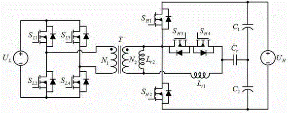
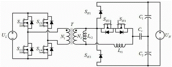
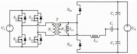
[0037] as attached figure 1 As shown, the bidirectional resonant DC converter is powered by the low-voltage side power supply U L , high voltage side power supply U H , the first switching tube S on the low-voltage side L1 , the second switching tube S on the low-voltage side L2 , the third switching tube S on the low-voltage side L3 , the fourth switching tube S on the low-voltage side L4 , Transformer T, the first switching tube S on the high voltage side H1 , the second switching tube S on the high vol...


PUM


Abstract

The invention discloses a bidirectional resonance DC converter and a control method thereof. The bidirectional resonance DC converter is formed by a low-voltage side power supply, a high-voltage side power supply, low-voltage side first switch tube-low-voltage side fourth switch tube, high-voltage side first switch tube-high-voltage side fourth switch tube, first and second resonant inductors, a resonant capacitor, first and second capacitors and a transformer. When energy is transmitted from the lower voltage side to the high voltage side, the bidirectional resonance DC converter realizes power control through phase-shifting control of the switch tubes at the two sides; and when the energy is transmitted from the high voltage side to the low voltage side, the bidirectional resonance DC converter realizes power control through frequency converting control of the switch tubes. The bidirectional resonance DC converter not only can realize bidirectional transmission and control of the energy at the two sides, but also can realize soft switching of all switch devices in full load range, and is especially suitable for being applied to high-frequency, high-efficiency and high-power-density two-way power transformation occasions.

Description

technical field [0001] The invention relates to a bidirectional resonant DC converter and a control method thereof, belonging to the technical field of power electronic converters, in particular to the technical field of bidirectional isolated DC-DC power conversion. Background technique [0002] Bidirectional DC converters can realize power transmission and control in two directions, and have the functions of two unidirectional DC converters. It has broad application prospects in power systems including energy storage links such as renewable energy power generation, electric vehicles, aerospace power supply, and smart grids. [0003] In various energy storage systems, the voltage of the energy storage battery is usually very low, while the voltage on the other side (such as the DC bus side) is usually high. How to achieve high-efficiency bidirectional power conversion in the case of a large voltage difference between the two sides is Important issues of domestic and foreig...

Claims


Application Information

Patent Timeline
IPC IPC(8): H02M3/335
Inventor 吴红飞韩蒙牟恬恬邢岩
Owner NANJING UNIV OF AERONAUTICS & ASTRONAUTICS
Learn More