Wet flue gas desulphurization dedusting tower and wet flue gas desulphurization dedusting method

A technology of wet desulfurization and dedusting tower, which is applied to chemical instruments and methods, separation methods, and separation of dispersed particles. It can solve problems such as difficulty in removal, difficulty in charging, and insufficient absorption of flue gas. Simple maintenance and high efficiency

Inactive Publication Date: 2016-01-06
ZHEJIANG HONGDIAN ENVIRONMENTAL PROTECTION & TECH CO LTD
View PDF0 Cites 3 Cited by
  • Summary
  • Abstract
  • Description
  • Claims
  • Application Information

AI Technical Summary

Problems solved by technology

[0009] There are three main reasons why the existing conventional desulfurization and denitrification technologies are difficult to achieve near-zero emissions: First, there are still a small amount of SO 2 The flue gas is not fully absorbed at the spray layer; the second is that the mechanical demister does not completely remove zero; the third is that the wettability of PM10 and below, especially ultrafine particles such as PM2.5, is poor and cannot be removed by the mechanical demister
The existing bag filter is also powerless to PM2.5 ultrafine particles due to the bag mesh and pressure loss limitation
Existing electrostatic precipitators are difficult to remove because of the high specific resistance of PM2.5 ultrafine particles and difficulty in charging.

Method used


Image

  • Wet flue gas desulphurization dedusting tower and wet flue gas desulphurization dedusting method
  • Wet flue gas desulphurization dedusting tower and wet flue gas desulphurization dedusting method
  • Wet flue gas desulphurization dedusting tower and wet flue gas desulphurization dedusting method

Examples


Embodiment 1

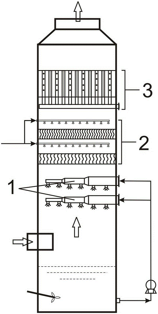
[0030] Such as figure 1 As shown, a flue gas wet desulfurization and dust removal tower includes a tower body, a spray layer 1, and a demister layer 2 above the spray layer. It is characterized in that a flue gas Special bubbling system for wet desulfurization and dust removal 3.

[0031] Such as Figure 4 , Figure 5 and Figure 6 As shown, the special bubbling system 3 for flue gas wet desulfurization and dust removal includes a number of flue gas pipes 31, bubbling pipes 32 on the side walls of the flue gas pipes 31, and a delivery subsystem 33 for absorbing wetting liquid. The bubbler tube 32 is provided with a liquid vapor bubble releasing device 321 in the form of a small hole, which is used to blow out the liquid bubbles into the flue gas tube 31. connect.

[0032] The flue gas pipe 31 in this embodiment is hexagonal, and a plurality of flue gas pipes 31 can form a seamless splicing, and the bubbling pipe 32 is just located at the splicing corner of the three flue ...

Embodiment 2

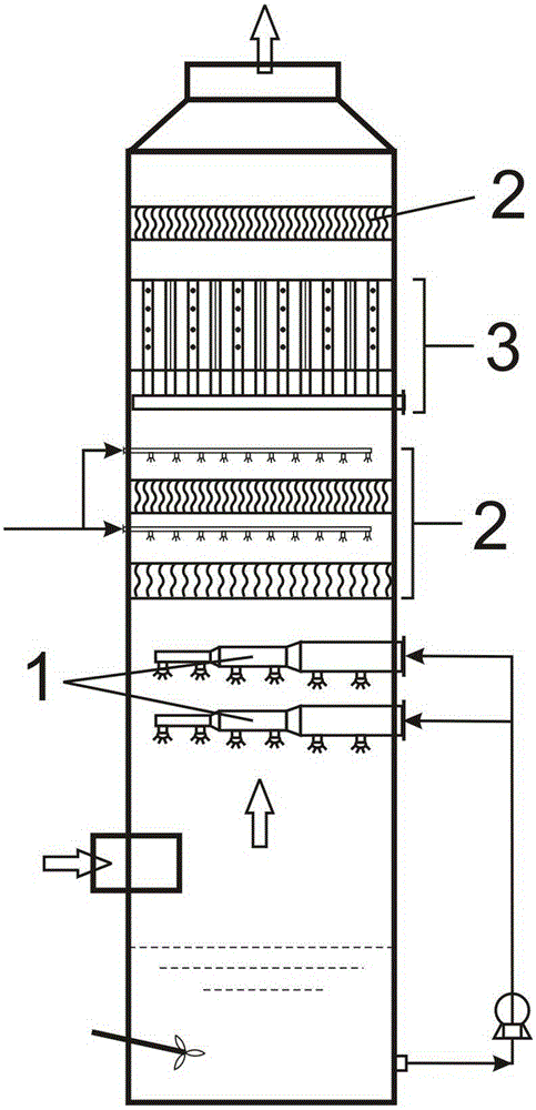
[0036] Such as figure 2 As shown, another flue gas wet desulfurization dedusting tower. The difference between the flue gas wet desulfurization and dedusting tower in this embodiment and embodiment 1 is that on the basis of embodiment 1, a layer of mist eliminator is set above the special bubbling system 3 for flue gas wet desulfurization and dust removal Layer 2. The function of this demister layer 2 is to intercept the mist entrained in the flue gas after passing through the special bubbling system 3 for flue gas wet desulfurization and dust removal, so as to further remove the residual SO in the flue gas 2 and ultrafine particulate matter.

[0037] Such as Figure 7 As shown, the flue gas pipe 31 in this embodiment is quadrangular, and a plurality of flue gas pipes 31 form a seamless splicing, and the bubbling pipe 32 is located at the center of the side wall of each flue gas pipe 31 . The size and number of flue gas pipes 31 are configured according to the size of the...

Embodiment 3

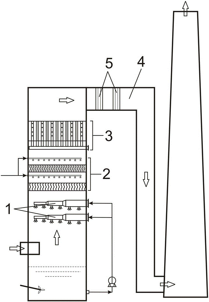
[0039] like water image 3 As shown, another flue gas wet desulfurization dedusting tower. The difference between the flue gas wet desulfurization and dedusting tower in this embodiment and embodiment 1 is that on the basis of embodiment 1, a horizontal flue 4 is set above the special bubbling system 3 for flue gas wet desulfurization and dust removal, and the The flue gas is led out of the desulfurization and dust removal tower, and then a special demister 5 for the flue is installed on the horizontal flue. The special demister for the flue is a more mature product.

[0040] Like embodiment 2, under the situation that a conventional mist eliminator layer 2 is arranged directly above the special bubbling system 3 for wet desulfurization and dust removal of flue gas, the mist droplets intercepted by the mist eliminator 2 gather into falling water droplets, and the water droplets fall When reaching the flue gas pipe 31 of the special bubbling system 3 for wet flue gas desulfur...


PUM


Abstract

The invention provides a wet flue gas desulphurization dedusting tower. The tower comprises a tower body, a spraying layer (1) and a demister layer (2) which is above the spaying layer. The tower is characterized in that: a bubbling system (3) special for wet flue gas desulphurization dedusting is arranged above the demister layer (2), wherein the bubbling system (3) special for wet flue gas desulphurization dedusting comprises several flue gas pipes (31) which are combined parallally, bubbling pipes (32) which are arranged between the flue gas pipes or on the pipe walls, and wetting liquid absorption and conveying subsystems (33); liquid steam bubble discharging apparatuses (321) are arranged on the bubbling pipes (32) and are used for discharging liquid steam bubbles to the flue gas pipes (31), and the lower ends or the upper ends of the bubbling pipes (32) are connected with the wetting liquid absorption and conveying subsystems (33). In the flue gas pipes (31), rising flue gas and dense steam bubbles are merged and blended, so that flue gas and steam bubbles are in full contact, a small amount of residual SO2 in the flue gas is absorbed, at the same time ultrafine particles in the flue gas are absorbed or wetted, so that the ultrafine particles either enter liquid, or agglomerate into droplets as a result of wetting, and separation becomes easier. The invention also relates to a wet flue gas desulphurization dedusting method by using the technology.

Description

technical field [0001] The invention relates to a desulfurization and dust removal equipment, in particular to a flue gas wet desulfurization and dust removal tower. The invention also relates to a flue gas wet desulfurization and dust removal method. technical background [0002] With the full development of global industrialization, environmental problems have become increasingly prominent, especially the use of a large amount of fossil fuels has led to increasingly serious air pollution problems, and acid rain and haze problems have endangered human existence. The sulfur dioxide and smoke emitted by coal-fired boilers are one of the most important sources of acid rain and haze. For this reason, the coal-fired boiler flue gas emission standards formulated by governments of various countries have made more and more stringent limits on the content of sulfur dioxide and soot. [0003] In recent years, my country's air pollution is also increasing. Since 2013, "smog" has be...

Claims


Application Information

Patent Timeline
Patent Type & Authority Applications(China)
IPC IPC(8): B01D50/00B01D53/18B01D53/78B01D53/50
Inventor 张文广邹可兴
Owner ZHEJIANG HONGDIAN ENVIRONMENTAL PROTECTION & TECH CO LTD
Why Eureka
Try Eureka