A method and equipment for electron beam smelting polysilicon deoxidation and continuous ingot casting

An electron beam smelting and polysilicon technology, which is applied in the field of metallurgical smelting, can solve the problems of difficult operation, long time consumption, and high risk, and achieve the effects of improving production efficiency, reducing time, and saving energy consumption

Inactive Publication Date: 2016-08-17
QINGDAO XINSHIJI SOLAR ENERGY TECH CO LTD
View PDF7 Cites 0 Cited by
  • Summary
  • Abstract
  • Description
  • Claims
  • Application Information

AI Technical Summary

Problems solved by technology

[0009] However, in the prior art, the removal effect of oxygen element is not good
For the removal method of oxygen impurities, the invention patent CN200810070925 was retrieved, a method for reducing the content of oxygen and carbon in metal silicon. The invention adopts blowing oxygen, hydrogen and water vapor into the silicon liquid to make hydrogen and oxygen react in the silicon liquid. Local high temperature is generated to remove oxygen and carbon elements in the silicon liquid with gas discharge, but this method needs to feed oxygen and hydrogen in the molten state of silicon, the operation is difficult and dangerous, and the oxygen removal effect is not good
[0010] At the same time, after effectively reducing the oxygen content in the polysilicon ingot raw material, the polysilicon ingot can be obtained through the directional growth process, but the previous ingot casting method is to directly heat the ingot raw material, which takes a long time and consumes a lot of energy. Continuous ingot casting cannot be realized, repeated vacuum extraction is required, and the energy consumption is relatively large

Method used


Image

  • A method and equipment for electron beam smelting polysilicon deoxidation and continuous ingot casting

Examples


Embodiment 1

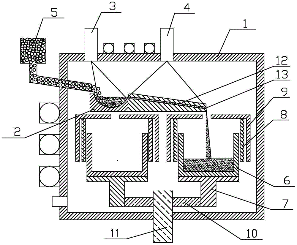
[0037] Such as figure 1 As shown, the equipment for electron beam smelting polysilicon deoxidation and continuous ingot casting includes a furnace body, and the furnace body 1 is provided with an electron beam smelting component and a continuous ingot casting component, wherein:

[0038] The electron beam melting assembly includes a water-cooled melting crucible 2 installed on the upper part of the furnace body. A concave melting pool (not shown in the drawings) is opened on the melting crucible. One side of the melting crucible is provided with a water-cooled conveyor belt 12. The water-cooled conveyor One side of the belt is flush with the side opening of the smelting crucible, and the other side is inclined downward and is provided with a diversion port 13, and a concave groove is opened on the water-cooled conveyor belt, which is used to guide the polysilicon liquid that is smelted and initially deoxidized to the ingot It flows in the direction of the device and enters the...

Embodiment 2

[0043] Adopt the device described in embodiment 1, carry out electron beam smelting polysilicon deoxidation and continuous ingot casting process,

[0044] Specific steps are as follows:

[0045] (1) Loading and vacuuming: Clean and dry the polysilicon material with a particle size of 10-12mm, a purity of 99.996%, and an oxygen content of 20ppmw, then put it into the feeding device, and lay 6N polysilicon at the bottom of the quartz crucible of the ingot casting device Ingot bottom material, and vacuum the furnace to 3×10 -2 Pa, the vacuum degree of the electron gun is pumped to 4×10 -3 Pa, preheat the electron gun for 15 minutes;

[0046] (2) Preliminary oxygen removal: Continuously add the polysilicon material in step (1) to the melting crucible of the electron beam melting furnace through the feeding device, start the electron gun for melting, set the electron beam current of the electron gun for melting to 1200mA and melt for 15 minutes Preliminary removal of impurity ox...

Embodiment 3

[0051] Adopt the device described in embodiment 1, carry out electron beam smelting polysilicon deoxidation and continuous ingot casting process,

[0052] Specific steps are as follows:

[0053] (1) Loading and vacuuming: Clean and dry the polysilicon material with a particle size of 24-30mm, a purity of 99.997%, and an oxygen content of 11ppmw, then put it into the feeding device, and lay 6N polysilicon at the bottom of the quartz crucible of the ingot casting device Ingot bottom material, and vacuum the furnace to 4×10 -2 Pa, the vacuum degree of the electron gun is pumped to 4.5×10 -3 Pa, preheat the electron gun for 13 minutes;

[0054] (2) Preliminary oxygen removal: Continuously add the polysilicon material in step (1) to the crucible of the electron beam melting furnace through the feeding device, start the electron gun for melting, set the electron beam current of the electron gun for melting to 800mA and melt for 5 minutes Preliminary removal of impurity oxygen in ...


PUM


Abstract

Belonging to the field of metallurgical melting, the invention in particular relates to a method and a device for electron beam melting to remove oxygen from polysilicon and continuous ingot casting. The method includes: subjecting a furnace body and an electron gun to vacuum pumping, starting a electron gun for melting to conduct electron beam melting on a polysilicon material, and preliminarily removing impurity oxygen; under the action of an electron gun for radiation, keeping a liquid state and further conducting oxygen removal, and finally leading the polysilicon liquid into ingot casting equipment through a water-cooled transmission belt to carry out a directional crystal growth ingot casting process so as to obtain a polysilicon cast ingot till the end of directional crystal growth ingot casting processes in all ingot casting equipment. The device includes an electron beam melting assembly and a continuous ingot casting assembly. The electron beam melting assembly comprises a water-cooled melting crucible and the water-cooled transmission belt disposed on one side of the melting crucible. 3-6 ingot casting equipment is fixedly mounted on a rotating platform. The invention puts forward the technological method and application of electron beam melting for oxygen removal, realizes the effects of oxygen removal by electron beams. At the same time, by combining continuous ingot casting, the energy consumption needed by heating the raw materials of ingot casting is reduced, and the production efficiency is greatly improved.

Description

technical field [0001] The invention belongs to the field of metallurgical smelting, in particular to a method for electron beam smelting of polysilicon for impurity removal and continuous ingot casting, and also relates to its equipment. Background technique [0002] At present, my country has become the world's largest energy production and consumption country, but the per capita energy consumption level is still very low. With the continuous development of the economy and society, my country's energy demand will continue to grow. In response to the current energy shortage, countries around the world are thinking deeply, and are working hard to improve energy efficiency, promote the development and application of renewable energy, and reduce the impact on energy consumption. Reliance on imported oil to enhance energy security. [0003] As one of the important development directions of renewable energy, solar photovoltaic power generation has developed rapidly in recent yea...

Claims


Application Information

Patent Timeline
Patent Type & Authority Patents(China)
IPC IPC(8): C30B28/06C30B29/06C01B33/037
Inventor 谭毅安广野郭校亮姜大川王登科
Owner QINGDAO XINSHIJI SOLAR ENERGY TECH CO LTD
Why Eureka
Try Eureka