Ultrasonic vibration assisted metal micro-molding forming device and its application method

An auxiliary metal and ultrasonic vibration technology, applied in forging/pressing/hammer devices, metal processing equipment, forging/pressing/hammering machinery, etc., can solve the problem of limited size of forming features, increased friction, insufficient microstructure filling, etc. problem, to achieve the effect of reducing the feature size, reducing friction, and avoiding the phenomenon of streamline cutting

Active Publication Date: 2017-12-22
SHANGHAI INST OF SATELLITE EQUIP
View PDF7 Cites 0 Cited by
  • Summary
  • Abstract
  • Description
  • Claims
  • Application Information

AI Technical Summary

Problems solved by technology

It can solve the problems that the friction force increases significantly with the reduction of the forming size, the filling of the microstructure is insufficient, and the forming feature size is limited in the micro-molding of materials.

Method used


Image

  • Ultrasonic vibration assisted metal micro-molding forming device and its application method

Examples


specific Embodiment approach 1

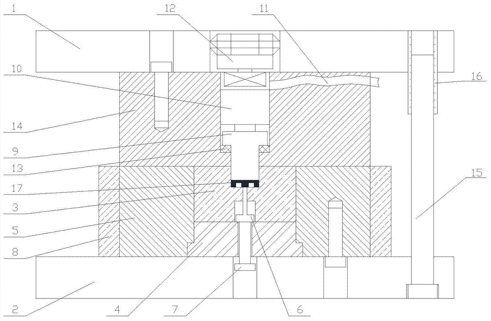
[0024] Specific implementation mode one: combine figure 1 To illustrate this embodiment, the present invention includes an upper mold base 1, a lower mold base 2, a die 3, a die backing plate 4, a die fixing plate 5, an ejector rod 6, an ejection screw 7, a heating ring 8, and a punch 9 , piezoelectric ceramics 10, high-frequency power supply 11, pressure sensor 12, butterfly spring 13, punch fixing plate 14, multiple guide posts 15 and guide sleeve 16, upper mold base 1 and lower mold base 2 are arranged in parallel, and lower mold base A plurality of guide pillars 15 are arranged around the seat 2, one end of each guide pillar 15 is set on the bottom end surface of the lower mold base 2, and the other end is slidingly arranged in the guide sleeve 16, and the guide sleeve 16 is arranged on the upper mold base 1. The die fixing plate 5 is arranged on the lower die base 2, on which a die mounting hole is arranged, the die backing plate 4 is arranged in the die mounting hole, an...

specific Embodiment approach 2

[0025] Specific implementation mode two: combination figure 1 Describe this embodiment, the ultrasonic vibration-assisted metal micro-molding forming device described in this embodiment includes a ejector mechanism, which is composed of a ejector rod 6 and an ejector screw 7. Pass through the lower die base 2 and the die backing plate 4 in turn to abut against the lower end surface of the ejector rod 6.

[0026] The technical effect of this embodiment is: the ejector mechanism in this embodiment plays the role of pushing out the micro-molding part 17 during the micro-molding process. After the micro-molding is completed, the pressure is applied to the ejector rod 6 by tightening the ejection screw 7 , Push out the formed micro-molded part 17.

specific Embodiment approach 3

[0027] Specific implementation mode three: combination figure 1 Describe this embodiment, the ultrasonic vibration assisted metal micro-molding forming device in this embodiment includes a heating device, the heating ring 8 is enveloped on the periphery of the die fixing plate 5, and the mold and the blank are heated to the blank forging temperature by the heating ring 8.


PUM


Abstract

The invention provides an ultrasonic vibration-assisted metal micro die forming device which comprises a lower die holder, a female die, a female die base plate, a female die fixing plate, an ejector rod, an ejection screw, a piezoelectric element, a male die, a male die fixing block and a pressure sensor, wherein the female die fixing plate is fixedly arranged on the upper surface of the low die holder, both the female die base plate and the female die are embedded into the female die fixing plate, the female die is fixedly arranged at the top of the female die base plate, the ejection screw penetrates through the center of the lower die holder and extends into the female die base plate, the ejector rod is arranged at the bottom of the female die, the male die fixing block is arranged at the top of female die fixing plate, the male die is embedded into the bottom of the male die fixing block, the piezoelectric element is arranged at the top of the male die, and the pressure sensor is arranged at the top of the piezoelectric element. The ultrasonic vibration-assisted metal micro die forming device has the advantages that a required micro die casting part can be formed directly with an ultrasonic vibration-assisted metal micro die forming method, secondary processing is avoided, the processing efficiency is improved, and the cost is low.

Description

technical field [0001] The invention relates to a material micro-molding forming device and method, in particular to a high-frequency vibration-assisted micro-molding forming device and method. Background technique [0002] With the rapid development of micro-electromechanical systems and micro-mechanisms, the demand for micro-components continues to increase, and the requirements for micro-forming quality are also increasing, requiring high geometric dimension accuracy and shape and position accuracy. Plastic micro-forming has obvious advantages in terms of processing efficiency, material utilization, manufacturing cost, part performance and dimensional accuracy. However, affected by the friction size effect, the friction force on the component during the micro-molding process increases significantly as the size decreases. , there is often the problem of incomplete filling of microstructures and limited size of forming features, which limits the wide application of micromol...

Claims


Application Information

Patent Timeline
Patent Type & Authority Patents(China)
IPC IPC(8): B21J5/02B21J13/02B21K29/00
CPCB21J5/006B21J5/02B21J13/02B21K29/00
Inventor 韩海波刘刚张丽新杨碧琦刘继超周博潘阳阳徐骏谢建华
Owner SHANGHAI INST OF SATELLITE EQUIP
Why Eureka
Try Eureka