Biocompatible Material for Surgical Implants and Cell Guiding Tissue Culture Surfaces

a technology of surgical implants and biocompatible materials, applied in the field of biocompatible materials, can solve the problems of increasing public health problems, implant loosening over time remains a significant problem, and term joint replacements, and achieve the effects of improving the differentiation of embryonic stem cells, promoting the growth of undifferentiated embryonic stem cells, and improving the quality of li

Inactive Publication Date: 2008-08-28
AARHUS UNIV
View PDF15 Cites 25 Cited by
  • Summary
  • Abstract
  • Description
  • Claims
  • Application Information

AI Technical Summary

Benefits of technology

[0024]Another type of structures that has provided good results are structures where the protrusions are positioned on grid points of a two-dimensional regular grid such that only a subset of grid points are covered by protrusions, i.e. some grid points are not covered by a protrusion. A similar advantageous effect has been observed when the regular grid is a hexagonal grid. In particular, good results have been achieved when the protrusions are arranged in parallel rows where the centre-to-centre distance between adjacent protrusions is different in adjacent rows. When the centre-to-centre distance between adjacent protrusions in every some rows is an integer multiple of the corresponding distance in the corresponding adjacent rows, flat areas are created surrounded by protrusions. In particular, when the protrusions of the rows with the larger centre-to-centre distances are aligned with the corresponding centers between protrusions of the adjacent rows, so as to be placed the protrusions on the corners of hexagons, these areas have a hexagonal shape which in turn has turned out t

Problems solved by technology

Degenerative disorders, cancer and trauma of the musculoskeletal apparatus constitute an increasing problem in public health.
Major advances and results have been achieved in this area during the last decades, but implant loosening over time continues to be a significant problem for successful long-term joint replacements.
The current implant surfaces are not able to bridge larger bone defects and maintain long-term stability alone.
Furthermore, as the near-future patient population will include a significant number of younger patients, the problem concerning long-term aseptic implant loosening is predicted to increase dramatically.
The biocompatibility/biointegration of an implant in the body is extremely complicated, involving processes traditionally belonging to medical science, surface science, materials science

Method used


Image

  • Biocompatible Material for Surgical Implants and Cell Guiding Tissue Culture Surfaces
  • Biocompatible Material for Surgical Implants and Cell Guiding Tissue Culture Surfaces
  • Biocompatible Material for Surgical Implants and Cell Guiding Tissue Culture Surfaces

Examples


example 1

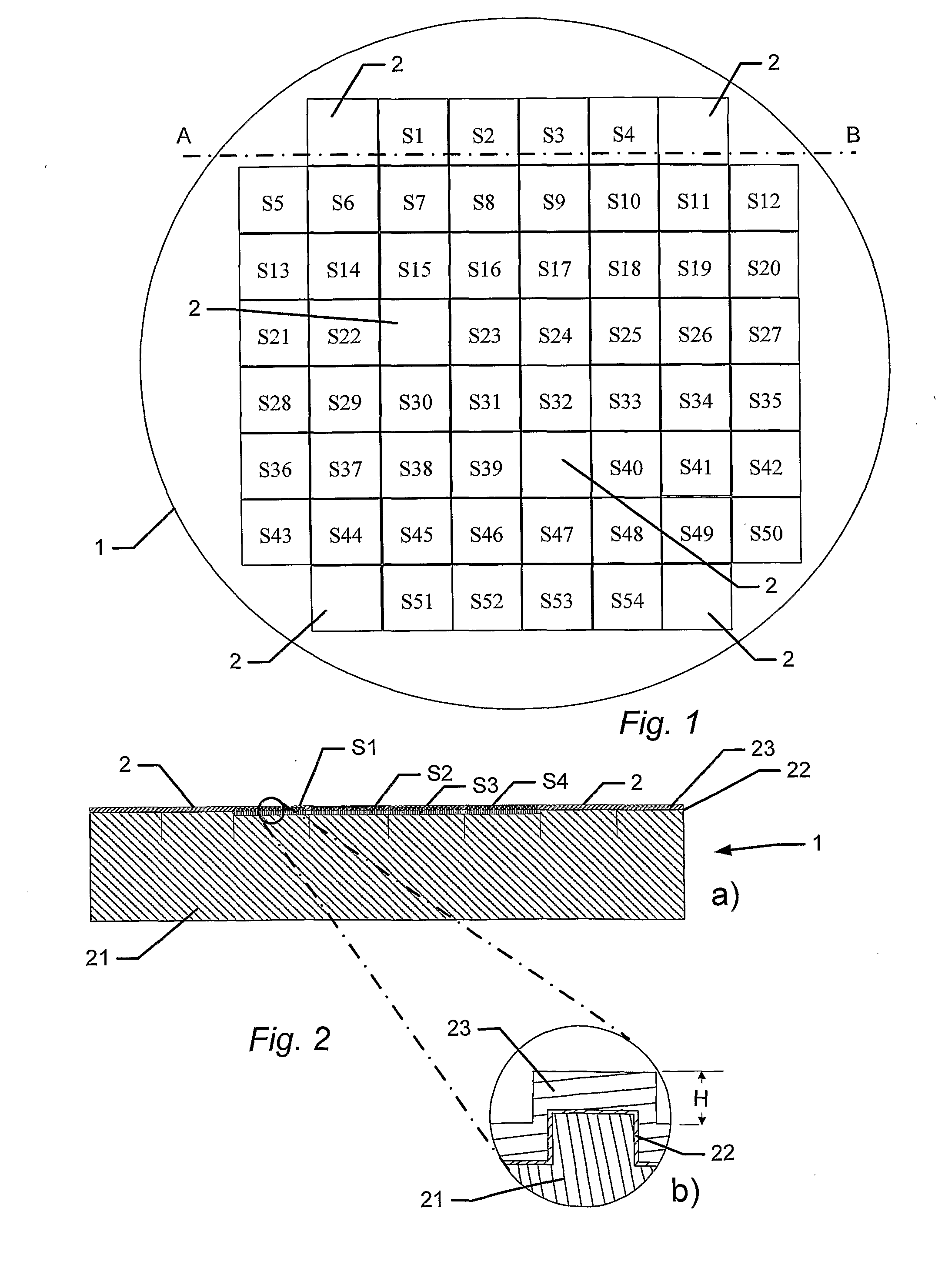
Manufacture of a 4 Inch BSSA Wafer Comprising 60 Tester Areas

[0126]A single-sided polished silicon wafer (4 inch) with a thickness of 525±25 μm provided a substratum for the manufacture of a biocompatible material. The wafer was an n-type wafer with a resistivity of 1-20 ohm cm. A micrometer-sized pattern was printed onto the polished side of the silicon wafer by standard photolithography and reactive ion etching in a SF6 / 02 discharge according to the following protocol:[0127]1. The wafers were pre-etched with buffered hydrofluoric acid (BHF, BHF is a solution of concentrated HF (49%), water, and a buffering salt, NH4F, in about the ratio 1:6:4) for 30 seconds and then dried under N2 flow, and[0128]2. the wafer was then spin-coated with a 1.5 μm thick layer of photoresist AZ5214, Hoechst Celanese Corporation, NJ, US (the chemical composition can be found at the Material Safety Data Sheet (MSDS) supplied by Hoechst Celanese Corporation). and pre-baked at around 90° C. for 120 seconds...

example 2

Screening a BSSA Wafer Identifies a Biocompatible Material for Mineralisation of Murine Osteoblastic Cells

[0142]A number of wafers were produced as described in connection with example 1. Each wafer was placed in a P15 dish (NUNC, Biotech line) and washed with 70% ethanol and then PBS (6.8 g NaCl, 0.43 g KH2PO4, 0.978 g Na2HPO4*2H2O in 1 liter double distilled water pH 7.4). The wafer was seeded with cells of a MC3T3-E1 murine osteoblastic cell line (Sudo, H et al. 1983, J Cell Biol 96 (1):191-98), at a concentration of 20,000 cells / cm2. The cells were cultured for 4 days in plain medium (alpha-minimal essential medium [α-MEM], 10% fetal calf serum [FCS], 100 U / ml penicillin, and 100 microgram / ml streptomycin (supplied by Gibco, Invitrogen). The cells were maintained in a humidified incubator (5% CO2 / 95% air atmosphere at 37° C.), and subsequently 284 μM ascorbic acid (Wako Chemicals, DE) and 10 mM β-glycerophosphate (Sigma-Aldrich, DK) were included in the growth medium. The cells ...

example 3

Identification of Biocompatible Surfaces for Mineralization of Osteogenic MC3T3 Cells

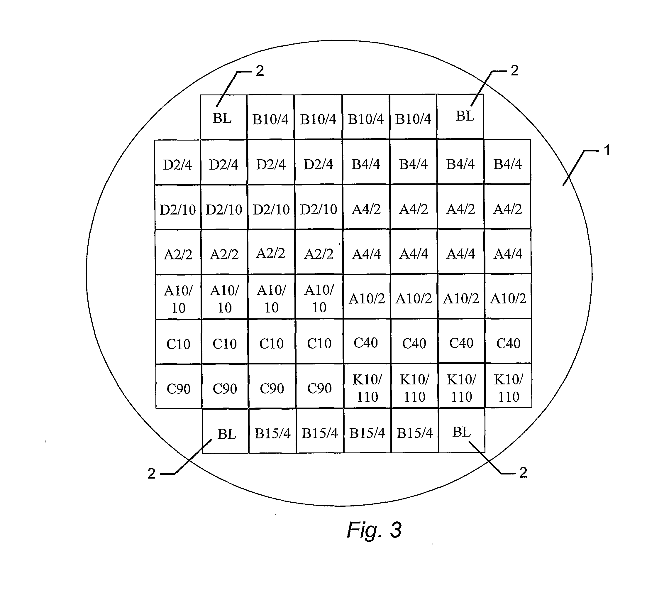
[0148]A BSSA wafer comprising tester squares having topographical structures selected from the structures identified in FIG. 12 or structures modified from the structures identified in FIG. 12, was prepared.

[0149]A wafer, comprising tester areas having the topographical structures shown in FIG. 12a-k, or structural modifications thereof, was seeded with MC3T3 cells, cultured, and subsequently stained for mineralization employing the alizarin red assay, as described in Example 2, and the level of mineralization was scored based on visual inspection. Images of surface structures found to be particularly favorable for mineralization, and thus shown to be biocompatible for bone-forming cells, are shown in FIG. 13. Each of FIGS. 13a-g shows a table, where each row corresponds to one of the identified structures. The first (left-most) column comprises identification codes for the respective structures, th...


PUM

PropertyMeasurementUnit
Lengthaaaaaaaaaa
Lengthaaaaaaaaaa
Lengthaaaaaaaaaa

Abstract

A biocompatible material, wherein at least a part of a surface of the biocompatible material is characterized by a micro or nano-meter scale topographical structure comprising a plurality of features where the structure is selected to promote a predetermined cell function in vivo or ex vivo in cell or tissue culture.

Description

TECHNICAL FIELD[0001]The present invention provides a biocompatible material having a surface structure and composition that affects a cellular function, in particular cellular functions related to bone cell mineralization and the formation of bone tissue, differentiation, in particular neuronal differentiation, of embryonic stem cells, and / or growth of embryonic stem cells, in particular of undifferentiated embryonic stem cells.BACKGROUND OF THE INVENTION[0002]The promotion of selected cellular functions is an important task in a variety of applications, such as the development of suitable implants, the productions of undifferentiated stem cells and / or the like. Biocompatible materials, on which living cells can attach, grow, and / or differentiate and / or further perform diverse biological functions, are desirable for a variety of therapeutic purposes.[0003]Degenerative disorders, cancer and trauma of the musculoskeletal apparatus constitute an increasing problem in public health. Sp...

Claims


Application Information

Patent Timeline
IPC IPC(8): A61F2/28C12N5/02B29C47/08
CPCG01N33/543G01N33/5005
Inventor BESENBACHER, FLEMMINGDUCH, MOGENS RYTTERGARDFOSS, MORTENPEDERSEN, FINN SKOUJUSTESEN, JEANNETTE HOFFMANN FRISCHANDERSEN, LARS KLEMBTCROVATO, TRINE ELKJAER LARSENMARKERT, LOTTE
Owner AARHUS UNIV
Why Eureka
Try Eureka