Laser scan filling system and scan filling method thereof

A laser scanning and filling system technology, applied in laser welding equipment, welding equipment, metal processing equipment, etc., can solve the problems of slow filling scanning speed and insufficient scanning accuracy, and achieve improved scanning efficiency and accuracy, high scanning accuracy and efficiency. and the effect of improving accuracy

Active Publication Date: 2016-01-06
武汉铱科赛科技有限公司
View PDF6 Cites 12 Cited by
  • Summary
  • Abstract
  • Description
  • Claims
  • Application Information

AI Technical Summary

Problems solved by technology

For example, in light-cured laser light-speed forming, for laser scanning of fine structures, the scanning speed of the laser galvanometer must be reduced to below 3 m / s to ensure the minimum scanning accuracy during laser filling. Otherwise, the filling scanning speed will increase, but the scanning accuracy Not enough, or the scanning accuracy is enough, and the filling scanning speed is too slow

Method used


Image

  • Laser scan filling system and scan filling method thereof
  • Laser scan filling system and scan filling method thereof
  • Laser scan filling system and scan filling method thereof

Examples


Embodiment 1

[0046] Embodiment 1. A laser scanning filling system. The following combination Figure 1-Figure 4-d The system provided in this embodiment will be described in detail.

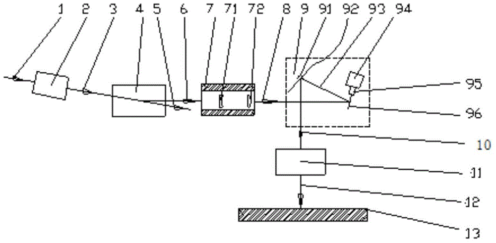
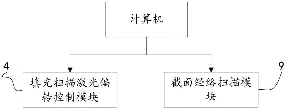
[0047] see figure 1 and figure 2 The system provided in this embodiment includes a computer, a laser focusing module 2 , a filling and scanning laser deflection control module 4 , a beam divergence and expansion optical module 7 , a section meridian scanning module 9 and a laser flat-field focusing module 11 .

[0048] The computer is used to control the real-time scan width range capability of the filling scanning according to the area and shape of the scanning section to be filled and the laser deflection control module 4 for filling and scanning, divide the scanning section to be filled into the filling area, and divide the filling area between two adjacent filling area lines Determine a scanning meridian line between them; it is also used to send the determined filling scanning range information to th...

Embodiment 2

[0067] Embodiment 2, a laser scanning filling system for silicon wafer laser milling blind slots, as shown in Figure 5, the device for silicon wafer laser milling blind slots includes a computer (not shown), laser focusing module 2, filling scanning laser Deflection control module 4 , beam divergence and expansion optical module 7 , section meridian scanning module 9 and laser flat-field focusing module 11 .

[0068] Wherein, the first laser beam 3 is a focused beam, and the filling and scanning laser deflection control module 4 uses piezoelectric ceramics (not shown in the figure) to drive a plane reflector to perform one-dimensional or two-dimensional deflection and reflection on the first laser beam 3. The ability to modulate the reflection of the laser beam at an angle can achieve a frequency of 10KHz or even higher. This very high modulation frequency makes the laser filling and scanning very fast.

[0069] The first laser beam 3 is incident on the piezoelectric ceramic d...

Embodiment 3

[0077] Embodiment 3, a laser scanning filling method. The following combination Figure 6 The method provided in this embodiment is described in detail.

[0078] see Figure 6 , the laser scanning filling method provided in this embodiment includes:

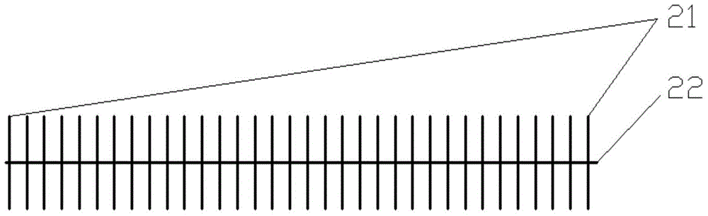
[0079] S1. According to the area and shape of the scanning section to be filled and the laser deflection control module of the filling scanning to control the real-time scanning width range capability of the filling scanning, the computer divides the scanning section to be filled into area lines, and determines a line between two adjacent filling area lines scanning the meridian lines; and sending the filling scanning range information determined according to the filling area lines to the filling scanning laser deflection control module and sending the meridian scanning position information to the section meridian scanning module.

[0080] Specifically, the computer first partitions the filling section to be scanned. When part...


PUM

PropertyMeasurementUnit
wavelengthaaaaaaaaaa
poweraaaaaaaaaa

Abstract

The invention discloses a laser scan filling system and a scan filling method thereof. The laser scan filling system comprises a computer, a laser focusing module, a filling scanning laser deflection control module, a beam divergence and expansion optical module, a section texture scanning module and a flat-field laser focusing module. According to the invention, a computer performs division of scan filling regions and division of scan texture paths on a section to perform filling scanning in advance, and controls the filling scanning laser deflection control module and the section texture scanning module to respectively perform filling scanning and texture scanning; filling speed scanning modulation and texture scanning movement modulation are simultaneously performed on laser beams by sufficient utilization of advantages of the section texture scanning module, especially the linear long-distance texture path scanning movement capability of a galvanometer and the local high-speed high-precision filling scanning movement of the filling scanning laser deflection control module, so that the breakthrough improvement of overall laser filling scanning efficiency and precision is obtained.

Description

technical field [0001] The invention relates to the technical field of laser processing, in particular to a laser scanning filling system and a scanning filling method thereof. Background technique [0002] In the field of laser processing, there is a part of processing that is a large-area laser scanning filling relative to the laser focus. There is no doubt that most of them currently use a galvanometer to scan the laser beam line by line. Laser focusing has front focus and back focus. In the two ways, in order to improve the laser filling speed, the acceleration and deceleration level of the galvanometer is also constantly improving, respectively from the aspects of software, circuit, material and shape design of the galvanometer lens, and innovation of the motor. However, since the movement of the galvanometer lens is a swing, Therefore, no matter how hard you try, the increase in the vibration speed of the galvanometer is getting closer and closer to the limit. If you ...

Claims


Application Information

Patent Timeline
Patent Type & Authority Applications(China)
IPC IPC(8): B23K26/082
Inventor 张立国
Owner 武汉铱科赛科技有限公司
Why Eureka
Try Eureka