Let-off mechanism, rapier loom comprising same, and control method for let-off mechanism

A warp let-off mechanism and warp let-off technology, applied in looms, textiles, textiles and papermaking, etc., can solve the problems of inconvenient installation and adjustment, large overall quality, no connection, etc., improve accuracy and stability, and avoid mutual entanglement , Guaranteed directional effect

Active Publication Date: 2016-01-06
HANGZHOU HUASHUI FABRICS
View PDF12 Cites 8 Cited by
  • Summary
  • Abstract
  • Description
  • Claims
  • Application Information

AI Technical Summary

Problems solved by technology

Independent warping is performed on the warp yarns with too small tension. However, the warp let-off structure of the loom with double warp beams is very complicated at present, and the operation of the loom is not stable enough, and the tension between the two warp beams cannot be adjusted. Effective control with low production efficiency
[0005] The patent document with the application number 201310693628.X discloses a new double warp beam rapier loom, including a frame, a warp let-off mechanism, a weft beating mechanism, a drive system, and a winding mechanism. Wallboard, the rear of the let-off mechanism is provided with a heald frame mechanism, the first let-off beam is horizontally fixed on the warp beam seat, and the two ends of the second let-off beam are fixed on the fixing device independent of the frame. Two warp let-off beams are arranged in parallel below the first warp let-off beam by a fixed bracket independent of the frame, and the first warp let-off beam and the second warp let-off beam are driven by an independent drive system. The double warp beams of this technical scheme are placed up and down, although It can save a certain amount of space, but combined with the actual situation, there are a large number of warp threads wound on the warp beam, and its overall mass is very large. The installation of the upper warp beam is inconvenient, and there is no connection between the upper and lower warp beams. Mechanism and drive system, for the entire rapier loom, increase the cost of use, and the installation and adjustment between multiple sets of mechanism systems is inconvenient. In this technical solution, the setting of the upper and lower drive motors can easily affect the operation of the rapier loom Stability. Although a series of means have been added to the technical solution to control stability, this virtually increases the complexity of the overall structure and installation cost, and is not conducive to adjustment. In summary, there is room for improvement in the existing technology place

Method used


Image

  • Let-off mechanism, rapier loom comprising same, and control method for let-off mechanism
  • Let-off mechanism, rapier loom comprising same, and control method for let-off mechanism
  • Let-off mechanism, rapier loom comprising same, and control method for let-off mechanism

Examples


Embodiment 1

[0046] refer to Figure 2 to Figure 10 The present invention will be further described.

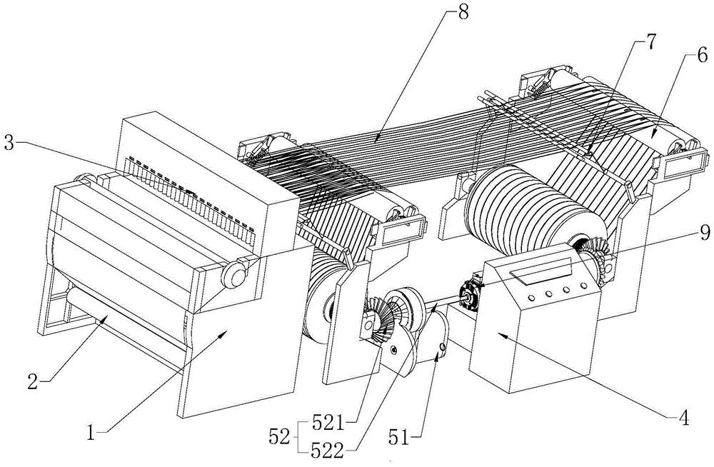
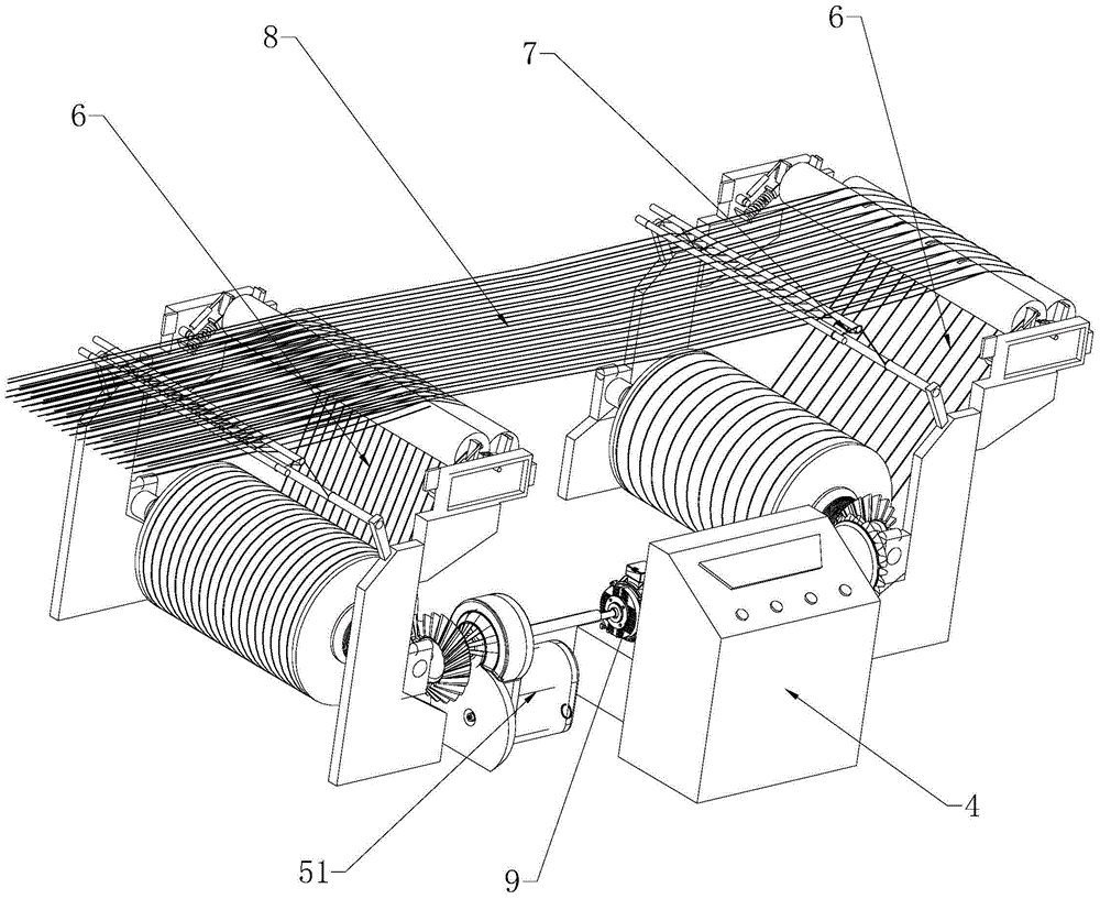
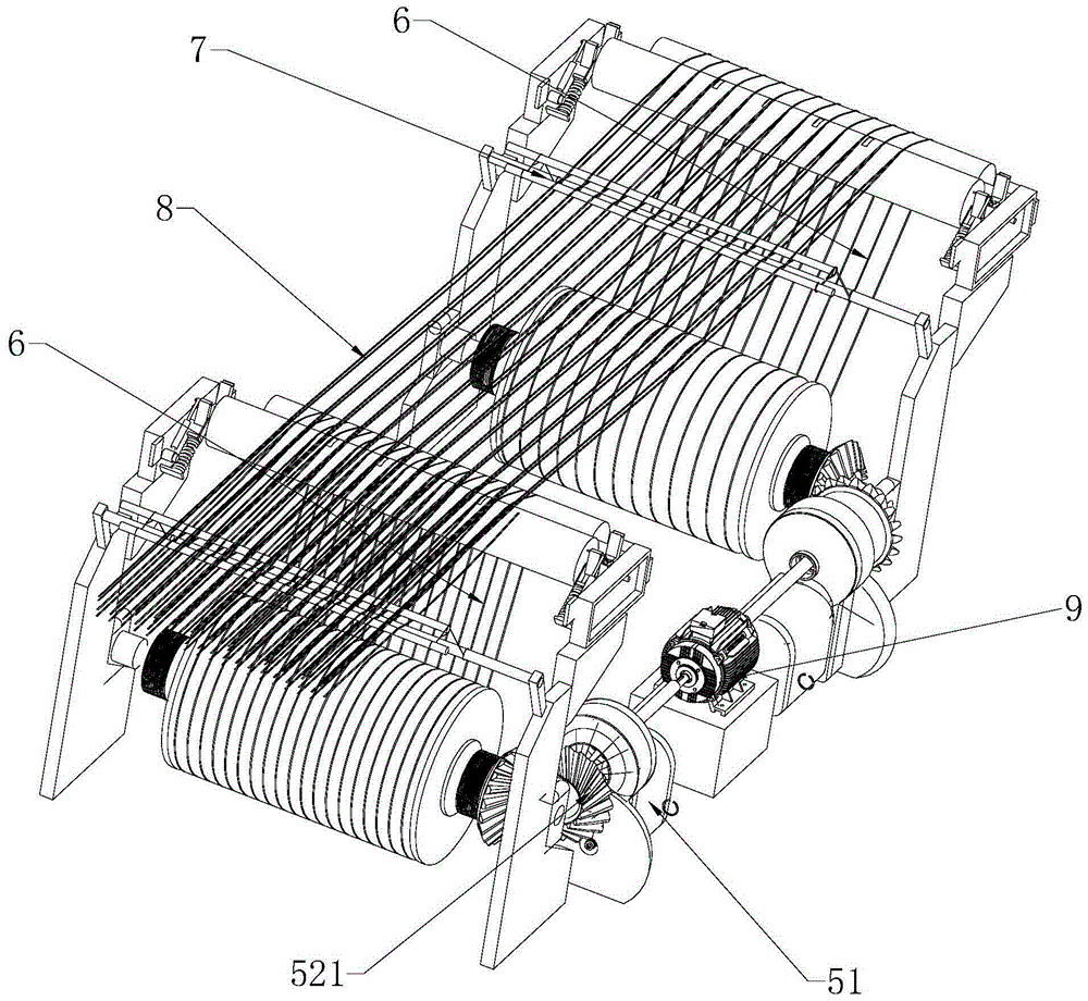
[0047] A warp let-off mechanism, comprising a controller 4 and at least two sets of warp let-off assemblies 6. In this embodiment, two sets of warp let-off assemblies 6 are selected, and the two sets of warp let-off assemblies 6 are arranged side by side in parallel. The warp assembly 6 all includes a warp let-off roller 11, a back beam 12, a dowel bar 13, left and right wall panels 10, and a tension detection unit 14, and the warp let-off roller 11, back beam 12, and dowel bar 13 are all fixed between the left and right wall panels 10 and Be arranged parallel to each other, when let-off, warp yarn 8 breaks away from the let-off roller 11 and passes through back rest 12 and dowel bar 13 successively, as Figure 8 As shown, the tension detection unit 14 includes a tension sensor 142 located on the dowel bar 13 and a tension spring 141 located at both ends of the dowel bar 13. One end of t...

Embodiment approach 1

[0049] Embodiment 1: A drive motor 9 is placed between two sets of let-off assemblies 6, the let-off assemblies 6 are divided into first and second let-off assemblies 6, and a speed changer is placed between the drive motor 9 and the first let-off assemblies 6. Box 51, one end of the drive motor 9 is connected to the gearbox 51 through a linkage rod 522, and the other end of the drive motor 9 is directly connected to the let-off roller 11 of the second let-off assembly 6 through a bevel gear set 521. The gearbox 51 and The let-off shafts on the first let-off assembly 6 are connected in transmission through a linkage rod 522 and a bevel gear set 521 .

Embodiment approach 2

[0050] Embodiment 2: A drive motor 9 is placed between two sets of let-off assemblies 6, and the let-off assemblies 6 are divided into first and second let-off assemblies 6. Between the drive motor 9 and the first let-off assembly 6 and the second let-off assembly A gearbox 51 is placed between the warp components 6, and the two ends of the drive motor 9 are respectively connected to two gearboxes 51 and connected through a linkage rod 522. The gearbox 51 and the warp let-off roller 11 are connected through a linkage rod 522 and a bevel gear set 521. Make drive connections.

[0051] Mode 1 and Mode 2 can both achieve the adjustment effect. Compared with Mode 1 and Mode 2, another gearbox 51 is needed, which saves cost, but the transmission ratio adjustment will also be limited accordingly. Considering the convenience of adjustment, Mode 2 is selected.

[0052] Such as Figure 9 As shown, the surface of each dowel bar 13 is provided with several grooves 131, the grooves 131 ar...


PUM


Abstract

The invention discloses a let-off mechanism, a rapier loom comprising the same, and a control method for the let-off mechanism. Compared with the prior art using individual control technology, the link between let-off mechanisms is enhanced; certain rotation speed ratios are provided for all let-off rollers through setting a transmission ratio for a speed changer; during a let-off process, intermediate driving values of the speeds of the multiple let-off rollers are obtained through the detection performed by sensors and the calculation performed by a controller, the mean value of the multiple intermediate driving values is worked out, and the rotation speed change of a driving motor is controlled according to the mean value; the improvement of the accuracy and stability of the rotation speed change is facilitated; the rotation speed change directions of the let-off rollers are the same all the time, so that the uniformity of the change tendencies of warp yarns on all the let-off rollers is facilitated; and the reduction of the influence, caused by the rotation speed change of the driving motor, on the instant tension of the warp yarns can be facilitated through a step of calculating the intermediate driving values and a step of calculating the result driving value, so that the stability of the tension of the warp yarns can be guaranteed and the tension tends to reach a preset value of the controller.

Description

technical field [0001] The invention relates to the field of textile equipment, more specifically, it relates to a warp yarn feeding equipment. Background technique [0002] The rapier loom is currently the most widely used shuttleless loom. In addition to the characteristics of high speed, high degree of automation, and high-efficiency production of the shuttleless loom, its positive weft insertion method has strong variety adaptability and can adapt to The weft insertion of various yarns, and the rapier loom also has obvious advantages in multi-color weft weaving, and can produce yarn-dyed products with up to 16 color weft yarns. As shuttleless looms replace shuttle looms, rapier looms will become the main production machine for woven fabrics. The rapier loom is composed of a warp beam, a warp let-off device, a working platform, a weft feeding device and a cloth winding device. The warp thread on the warp beam enters the working platform through the warp let-off device, a...

Claims


Application Information

Patent Timeline
Patent Type & Authority Applications(China)
IPC IPC(8): D03D49/10
Inventor 郭法水
Owner HANGZHOU HUASHUI FABRICS
Why Eureka
Try Eureka