Head transmission mechanism of computer-controlled flat-bed knitting machine

A technology of transmission mechanism and flat knitting machine, which is applied in knitting, weft knitting, textiles and papermaking, etc. It can solve the problems of low manufacturing efficiency, many transmission links, and heavy shape and structure, so as to achieve reasonable shape and structure and improve transmission efficiency , the effect of stable support

Inactive Publication Date: 2016-01-06
JIANGSU JINLONG TECHNOLOGY CO LTD
View PDF8 Cites 2 Cited by
  • Summary
  • Abstract
  • Description
  • Claims
  • Application Information

AI Technical Summary

Problems solved by technology

[0004] The above-mentioned document A is known to have the advantages of reducing the inflection point of the synchronous belt and adopts a structure of two-stage synchronous belt and synchronous belt gear transmission. It needs three synchronous belts to drive the movement of the machine head, so the transmission relationship is relatively complicated, and the actuation force loss is large due to many transmission links, which is not conducive to energy saving
Compared with document A, the above-mentioned documents B and C can make up for the aforementioned deficiencies of document A to a certain extent due to the use of two synchronous belts to move, but neither document B nor C provides a synchronous pulley with a synchronous belt However, the synchronous pulley seat should not only reflect the convenience of its installation with the frame beam, but also reflect its own machinability, etc.
[0005] The aforementioned synchronous pulley seat in the prior art usually appears in the form of iron castings, which are not only complicated in casting process, but also low in manufacturing efficiency, heavy and monotonous in shape and structure

Method used


Image

  • Head transmission mechanism of computer-controlled flat-bed knitting machine
  • Head transmission mechanism of computer-controlled flat-bed knitting machine

Examples


Embodiment

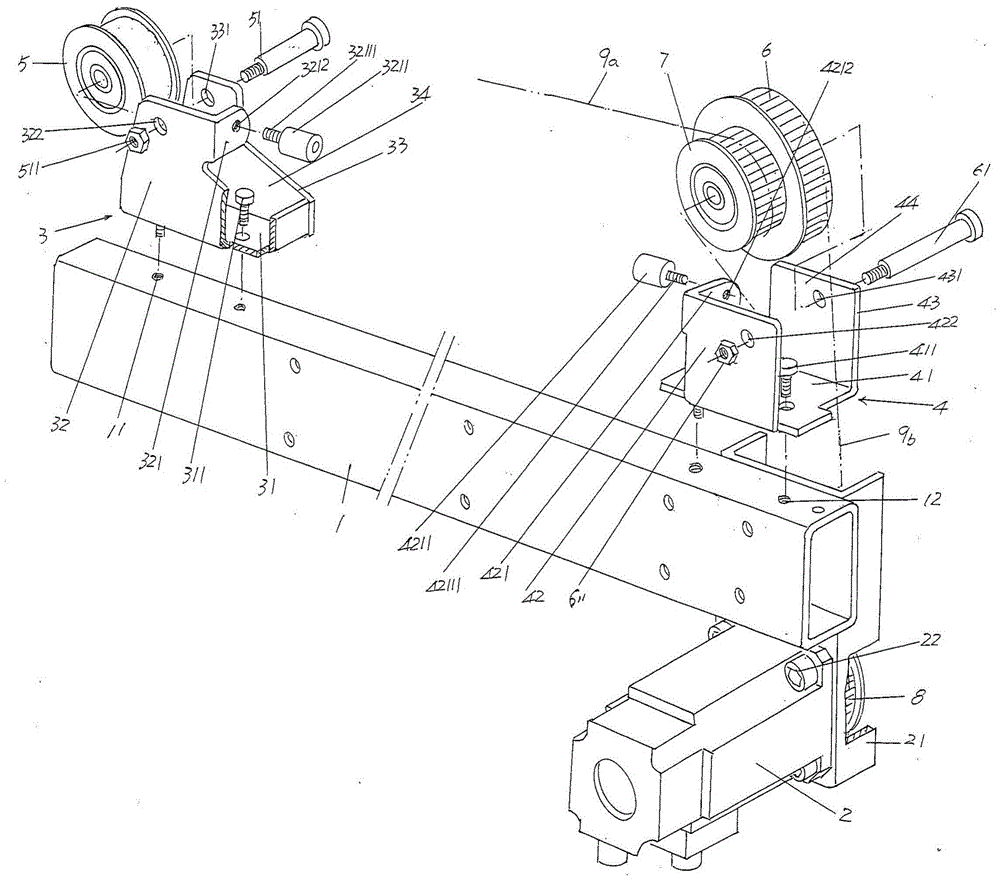
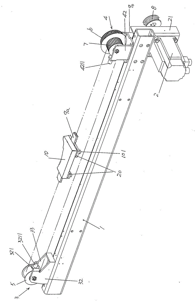
[0021] See figure 1 , provides a frame beam 1 belonging to the structural system of the computerized flat knitting machine, provides a motor 2 belonging to the structural system of the head drive mechanism of the present invention, and the motor 2 is horizontally cantilevered through the motor fixing seat 21 The state is fixed on the bottom right end of the frame crossbeam 1, specifically: the motor 2 and the lower part of the motor holder 21 are fixed with the motor fixing screw 22, and the upper part of the motor holder 21 is welded to the right end rear side of the frame crossbeam 1 Fixed; a left drive pulley seat 3, the left drive pulley seat 3 is fixed with the frame beam 1 at a position above the left end corresponding to the aforementioned frame beam 1; a right drive pulley seat 4, the right drive pulley seat 4 is in the corresponding The position above the right end of the aforementioned frame machine beam 1 is fixed with the frame beam 1; a left drive pulley 5, which ...


PUM


Abstract

The invention provides a head transmission mechanism of a computer-controlled flat-bed knitting machine, and belongs to the technical field of knitting machinery. The computer-controlled flat-bed knitting machine comprises a frame transversal beam. The head transmission mechanism comprises a motor, a left driving belt wheel seat, a right driving belt wheel seat, a left driving belt wheel, a right driving belt wheel, a traction driving belt wheel, a motor driving belt wheel, a traction driving belt and a main driving belt. The head transmission mechanism is characterized in that the left driving belt wheel seat is composed of a left driving belt wheel seat bottom board, a left driving belt wheel seat front side board and a left driving belt wheel seat rear side board; and the right driving belt wheel seat is composed of a right driving belt wheel seat bottom board, a right driving belt wheel seat front side board and a right driving belt wheel seat rear side board. The transmission efficiency is raised, the production efficiency is raised, the weight is reduced, material consumption is saved, and the left driving belt wheel, the right driving belt wheel and the traction driving belt wheel can be smoothly supported.

Description

technical field [0001] The invention belongs to the technical field of knitting machinery, and in particular relates to a head transmission mechanism of a computerized flat knitting machine. Background technique [0002] As known in the industry, the aforementioned machine head is the core component of the structural system of the knitting mechanism of the computerized flat knitting machine, because the triangular bottom plate with the cam system is fixed on the machine head, and the reciprocating movement of the machine head drives the corresponding movement of the triangular bottom plate , so that the knitting needles arranged in the needle grooves of the needle bed are forced to move up and down regularly by the cam system, and the yarn is woven into fabric through the action of the needle hook and the needle latch at the head of the knitting needle. [0003] The technical information about the aforementioned head transmission mechanism can be found in the published Chine...

Claims


Application Information

Patent Timeline
Patent Type & Authority Applications(China)
IPC IPC(8): D04B15/96
Inventor 金永良张和中孙健海港张金良
Owner JIANGSU JINLONG TECHNOLOGY CO LTD
Why Eureka
Try Eureka