
Enhanced heat exchange type heat pump system

A technology of heat pump system and enhanced heat exchange, which is applied in the direction of heat pump, fluid heater, refrigeration and liquefaction, etc. It can solve the problems of increasing equipment accident rate, increasing control difficulty, high manufacturing cost, etc., and achieves energy saving and applicability improvement and reduction Difficulty of installation, low maintenance rate, and low production cost

Inactive Publication Date: 2016-01-06
广州润达环保科技有限公司
View PDF10 Cites 1 Cited by
  • Summary
  • Abstract
  • Description
  • Claims
  • Application Information

AI Technical Summary

Problems solved by technology

However, there are the following disadvantages: firstly, the dual energy is realized by three-way valves, and the three-way valves required for switching will inevitably increase the cost, increase the equipment accident rate, and increase the difficulty of control; There are two kinds of refrigerant heat exchange tubes, which not only have high manufacturing costs, but also are difficult to install, and the disassembly and movement will cause refrigerant leakage

Method used


Image

  • Enhanced heat exchange type heat pump system
  • Enhanced heat exchange type heat pump system
  • Enhanced heat exchange type heat pump system

Examples


Embodiment 1

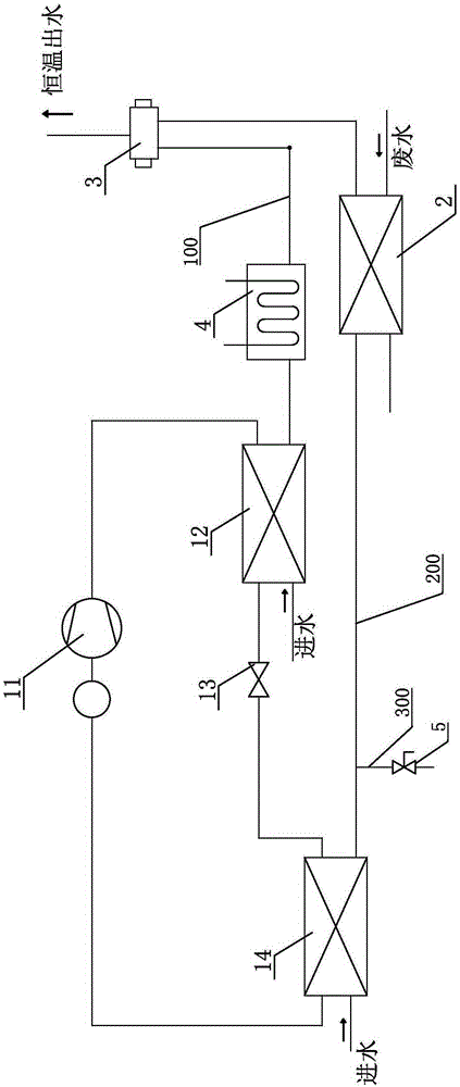
[0021] refer to figure 1 , the enhanced heat exchange heat pump system of the present invention includes a heat pump device, a waste heat exchanger 2, a first water inlet pipe 100 and a second water inlet pipe 200, and the heat pump device includes a compressor 11, a condenser 12, and a throttling device 13 , the evaporator 14 and the liquid accumulator, the compressor 11, the condenser 12, the throttling device 13, the evaporator 14 and the liquid accumulator form a closed loop through the refrigerant pipeline, and the first water inlet pipe 100 is connected to the water source and connected to all The condenser 12, the second water inlet pipe 200 is connected to a water source and communicated with the evaporator 14 and the waste heat exchanger 2. Here, the waste heat exchanger 2 can be either a heat exchanger for absorbing waste water heat energy or a heat exchanger for absorbing waste gas heat energy.

[0022] When the present invention works, the refrigerant circulates i...

Embodiment 2

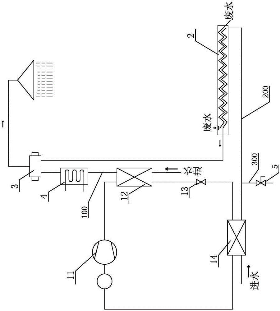
[0027] refer to figure 2 , which is different from Embodiment 1 in that the output end of the mixing valve 3 is connected with a shower for recovery of hot water and waste heat in the bathroom.

Embodiment 3

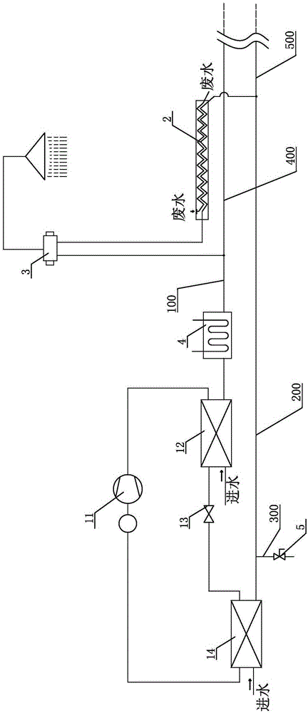
[0029] refer to image 3 , which is different from Embodiment 2 in that the first water inlet pipe 100 is connected with a hot water output branch 400 behind the condenser 12 to facilitate the output of the hot water flow formed after the heat exchange between tap water and the condenser 12 use.

[0030] The second water inlet pipe 200 is connected with a cold water output branch 500 between the evaporator 14 and the waste heat exchanger 2 , so as to facilitate the output of the cold water flow formed after the heat exchange between the tap water and the evaporator 14 .


PUM


Abstract

The invention discloses an enhanced heat exchange type heat pump system which comprises a heat pump device, a waste heat exchanger, a first water inlet pipe and a second water inlet pipe. The heat pump device comprises a compressor, a condenser, a throttling device, an evaporator and a liquid accumulator. A closed loop is formed by the compressor, the condenser, the throttling device, the evaporator and the liquid accumulator through a refrigerant pipeline. The first water inlet pipe is connected with a water source and communicated with the condenser. The second water inlet pipe is connected with the water source and communicated with the evaporator and the waste heat exchanger. According to the structure, before entering the waste heat exchanger, water flow in the second water inlet pipe is cooled in the mode that heat is extracted by the heat pump device, so that the heat exchange effect is greatly enhanced, and the energy saving performance and applicability of equipment are improved; meanwhile, refrigerants flow in the heat pump device circularly and do not enter the waste heat exchanger, the structure is simple, the production cost is low, the mounting difficulty and the maintenance rate are greatly reduced, and the requirements for onsite operation and application are met; besides, the water flow, with waste heat being recycled, in the second water inlet pipe does not need to return to the condenser to be heated, so that pipeline backflow and pressure loss are reduced.

Description

technical field [0001] The invention relates to an enhanced heat exchange heat pump system for recovering waste heat. Background technique [0002] Using the heat pump system to fully recover the waste heat to heat the incoming water is a highly efficient and energy-saving product. For example, the Chinese patent with the patent number CN201120478929.7 discloses an energy storage water source heat pump water heater that can double absorb waste heat from shower waste water. It first uses waste water to exchange heat with tap water, and then uses waste water as a heat source to supply the refrigerant for the refrigeration system. Absorption, to achieve double recovery of shower hot water, the heat exchange effect of the equipment is better. However, the two-stage shower waste heat recovery device described in this structure - the shower recovery device has two built-in pipelines (cold water pipe and refrigerant pipe), which makes the equipment relatively cumbersome, not only ...

Claims


Application Information

Patent Timeline
Patent Type & Authority Applications(China)
IPC IPC(8): F24H4/02F25B30/06
Inventor 平武臣
Owner 广州润达环保科技有限公司
Learn More