
Rock soil seepage monitoring sensor and manufacturing method

A technology for monitoring sensors and seepage, which is used in fluid velocity measurement, fluid resistance measurement, instruments, etc. It can solve the problems of continuous monitoring of difficult-to-integrate sensors and high cost, and achieve the effects of simple structure, small measurement distance and small volume.

Inactive Publication Date: 2016-01-06
WUHAN INSTITUTE OF TECHNOLOGY
View PDF7 Cites 5 Cited by
  • Summary
  • Abstract
  • Description
  • Claims
  • Application Information

AI Technical Summary

Problems solved by technology

In the traditional tracer method, since the tracer is mostly a dye or an electrolyte solution, a special dosing device is required, and the dosing point and the measurement location must be separated by a long distance, so it is difficult to design an integrated sensor to achieve continuous monitoring; The temperature field changes to determine the seepage velocity and flow direction. The fiber optic temperature measurement and seepage monitoring system is a typical representative of this type. Since the fiber optic temperature measurement and seepage monitoring system needs to lay optical fibers within the monitoring range, the cost is relatively high

Method used


Image

  • Rock soil seepage monitoring sensor and manufacturing method
  • Rock soil seepage monitoring sensor and manufacturing method
  • Rock soil seepage monitoring sensor and manufacturing method

Examples


example 1

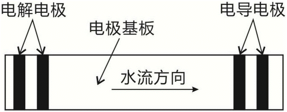
[0027] Example 1: Measure the conductivity at 50-1500μScm -1 Natural water between, flow rate range 0.01cms -1 -0.1cms -1 , a flow velocity measurement sensor with a fixed direction and a preparation method thereof,

[0028] Such as figure 1 As shown, the sensor includes a substrate and a pair of electrolytic electrodes and one or more pairs of conduction electrodes fixedly arranged on the substrate;

[0029] The electrolytic electrodes are used to generate electrolytic polarization;

[0030] The conductivity electrode is used to measure the conductivity of the system;

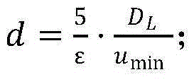
[0031] Take the minimum flow rate u min =0.01cm·s -1 ,D L =10 -5 cm 2 ·s -1 , ε=1%, calculate the minimum distance d between the electrolytic electrode and the conductance electrode, d = 5 ϵ · D L u min = 0.5 c ...

example 2

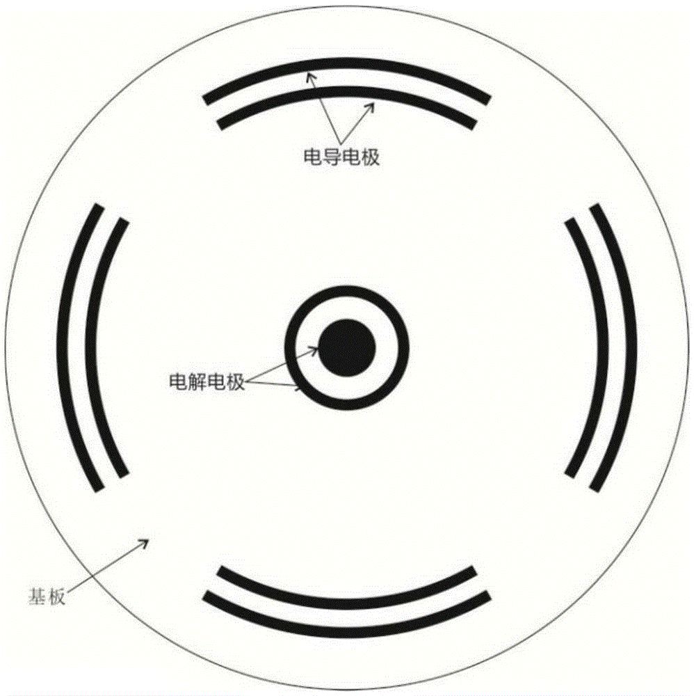
[0041] Example 2: Measure the conductivity at 50-1500μScm -1 Natural water between, flow rate range 0.01cms -1 -0.1cms -1 , Flow rate measurement sensor with non-fixed direction and preparation method.

[0042] Such as figure 2 As shown, the sensor includes a substrate and a pair of electrolytic electrodes and one or more pairs of conduction electrodes fixedly arranged on the substrate;

[0043] The electrolytic electrodes are used to generate electrolytic polarization;

[0044] The conductivity electrode is used to measure the conductivity of the system;

[0045] Take the minimum flow rate u min =0.01cm·s -1 ,D L =10 -5 cm 2·s -1 , ε=1%, calculate the minimum distance d between the electrolytic electrode and the conductance electrode, d = 5 ϵ · D L u min = 0.5 c m ...


PUM

PropertyMeasurementUnit
thicknessaaaaaaaaaa
distanceaaaaaaaaaa
thicknessaaaaaaaaaa

Abstract

The invention discloses a rock soil seepage monitoring sensor and a manufacturing method. The sensor manufacturing method comprises the following steps: (1) the distance between an electrolysis electrode and a conductance electrode is calculated and determined; (2) the material, the shape and the size of a substrate are determined; (3) the material, the shape and the size of the electrolysis electrode are determined; (4) the material, the shape, the size and the number of the conductance electrode are determined; and (5) manufacturing and fixing of the electrodes are carried out. The sensor manufactured by the invention has a simple structure, small size and low cost, no new materials are introduced during a tracing process, no environmental pollution exists, the measurement distance needed by the method is small, and flow velocity components in multiple directions can be determined simultaneously.

Description

technical field [0001] The invention relates to the technical field of rock and soil seepage monitoring, in particular to a rock and soil seepage monitoring sensor and a preparation method. Background technique [0002] Seepage flow direction and flow velocity are very important parameters in the fields of geotechnical engineering and hydrogeology, and are also of great significance to the research of pollutant migration, oil and gas development, water and soil erosion and other related issues. In the traditional tracer method, since the tracer is mostly a dye or an electrolyte solution, a special dosing device is required, and the dosing point and the measurement location must be separated by a long distance, so it is difficult to design an integrated sensor to achieve continuous monitoring; The temperature field changes to determine the seepage velocity and flow direction. The fiber optic temperature measurement and seepage monitoring system is a typical representative of ...

Claims


Application Information

Patent Timeline
Patent Type & Authority Applications(China)
IPC IPC(8): G01P5/00G01R27/22
Inventor 秦孙巍邱丹丹孙静月李先福李云安
Owner WUHAN INSTITUTE OF TECHNOLOGY
Learn More