

Frequency-division oscillator-based switching power supply for realizing frequency modulation
A frequency modulation and switching power supply technology, applied in the electronic field, can solve the problems of increasing duty cycle, wide voltage regulation range, low conversion efficiency, etc., and achieve the effect of reducing ripple and stabilizing cycle
Active Publication Date: 2016-01-06
SPREADTRUM COMM (SHANGHAI) CO LTD
View PDF5 Cites 2 Cited by
- Summary
- Abstract
- Description
- Claims
- Application Information
AI Technical Summary
Problems solved by technology
[0002] The power supplies used by modern electronic equipment are roughly divided into two categories: linear regulated power supply and switching regulated power supply. The linear regulated power supply is that its adjustment tube works in the amplification area. This kind of regulated power supply will not introduce additional interference, but its volume is relatively small. Large, the power mainly depends on the transformer and power tube, and the conversion efficiency is low; compared with the linear regulated power supply, the switching power supply has the characteristics of small power consumption, small size, and wide voltage regulation range. The switching power supply uses modern power electronics technology, and the control The time ratio of switching devices to turn on and off to maintain a stable output voltage. Pulse frequency modulation is usually used in switching power supplies to improve light load efficiency. Switching power converters operating in power-saving mode are used under light load current conditions. Pulse frequency modulation mode, use pulse width modulation mode under heavier load current conditions
However, because the control method of pulse frequency modulation is not easy, it is not as widely used in switching power supply circuits as pulse width modulation
In the prior art, in order to improve the circuit efficiency under light load or standby conditions, a low power consumption mode is set, also called: SkipCycleMode, when the circuit is under light load or standby conditions, the PWM controller is controlled Intermittently send out pulse signals to improve the efficiency of light load and standby by reducing the number of switches and increasing the duty cycle at a constant frequency. The waveform of the pulse modulation signal PFM1 in skip cycle control mode is shown in figure 1 As shown, however, this method will cause higher output ripple, and the control method is not ideal
Method used
View moreImage
Smart ImageViewing Examples


Examples
specific Embodiment
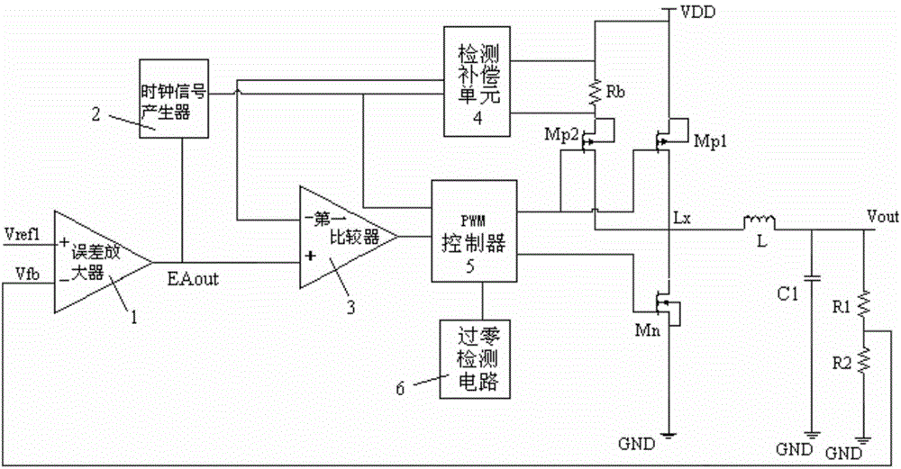
[0072] In a specific embodiment, the feedback network includes a first resistor R1 and a second resistor R2 connected in series, and the feedback voltage signal is drawn from a node where the first resistor R1 and the second resistor R2 are connected.
[0073] As a preferred embodiment of the present invention, the current detection circuit includes:
[0074] A detection resistor Rb, connected in series with the current detection circuit;
[0075] A detection compensation unit 4, connected to both ends of the detection resistor Rb, to detect the current flowing through the detection resistor;
[0076] A detection control switch Mp2 controlled on and off by the pulse modulation signal is connected to the current detection circuit.
Login to View More PUM
 Abstract
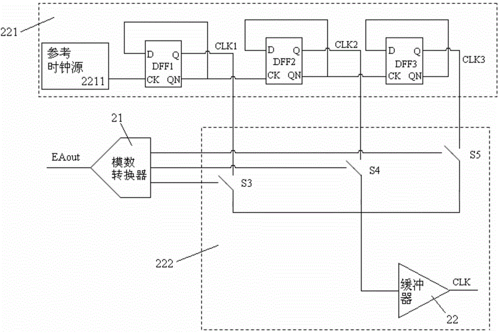
The invention provides a frequency-division oscillator-based switching power supply for realizing the frequency modulation and relates to a switching power supply circuit. The switching power supply comprises an operating circuit with an energy storage element and switched between the charging mode and the discharging mode under the effect of a pulse modulation signal, a control circuit used for generating the pulse modulation signal according to a reference voltage, a voltage feedback signal, a current detection signal and a clock signal, a clock signal generator, and a selection unit. The control circuit comprises an error amplifier used for obtaining an error amplifying signal. The clock signal generator comprises a clock frequency-division unit used for generating a plurality of clock signals different in frequency under the effect of a reference clock source. The selection unit is used for selecting one clock signal out of the plurality of clock signals under the effect of the error amplifying signal and then outputting the selected clock signal to the control circuit. According to the invention, a plurality of clock signals of preset frequencies are generated by a frequency-division oscillator. After that, one clock signal of a preset frequency is selected within a preset period of time according to the error amplifying signal and then is outputted to the control circuit. In this way, the period is stable and the ripple waves of the output voltage are reduced.
Description
technical field [0001] The invention relates to the field of electronic technology, in particular to a switching power supply circuit. Background technique [0002] The power supplies used by modern electronic equipment are roughly divided into two categories: linear regulated power supply and switching regulated power supply. The linear regulated power supply is that its adjustment tube works in the amplification area. This kind of regulated power supply will not introduce additional interference, but its volume is relatively small. Large, the power mainly depends on the transformer and power tube, and the conversion efficiency is low; compared with the linear regulated power supply, the switching power supply has the characteristics of small power consumption, small size, and wide voltage regulation range. The switching power supply uses modern power electronics technology, and the control The time ratio of switching devices to turn on and off to maintain a stable output v...
Claims
Login to View More Application Information
Patent Timeline
 IPC IPC(8): H02M3/07
Inventor樊茂
OwnerSPREADTRUM COMM (SHANGHAI) CO LTD