Switch mode power supply with a cascode circuit

A technology of switching power supply and amplifier, applied in the field of switching power supply, can solve the problems of increasing switching loss and line loss, etc.

Inactive Publication Date: 2016-01-06
PHOENIX CONTACT GMBH & CO KG +1
View PDF12 Cites 0 Cited by
  • Summary
  • Abstract
  • Description
  • Claims
  • Application Information

AI Technical Summary

Problems solved by technology

However, when modern high-voltage MOSFETs operate in the switching frequency range of

Method used


Image

  • Switch mode power supply with a cascode circuit
  • Switch mode power supply with a cascode circuit
  • Switch mode power supply with a cascode circuit

Examples


Embodiment Construction

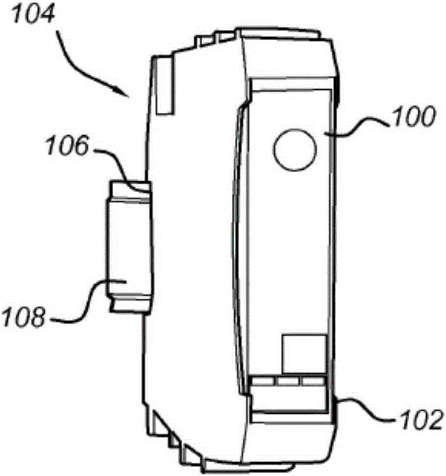
[0083] figure 1 A switching power supply is shown as an exemplary embodiment of electrical assembly 100 . The electrical assembly 100 has a housing 102 . In this exemplary embodiment, the housing 102 has a locking device 106 disposed on the rear side 104 thereof. The housing is locked on the top hat rail 108 through the locking device.

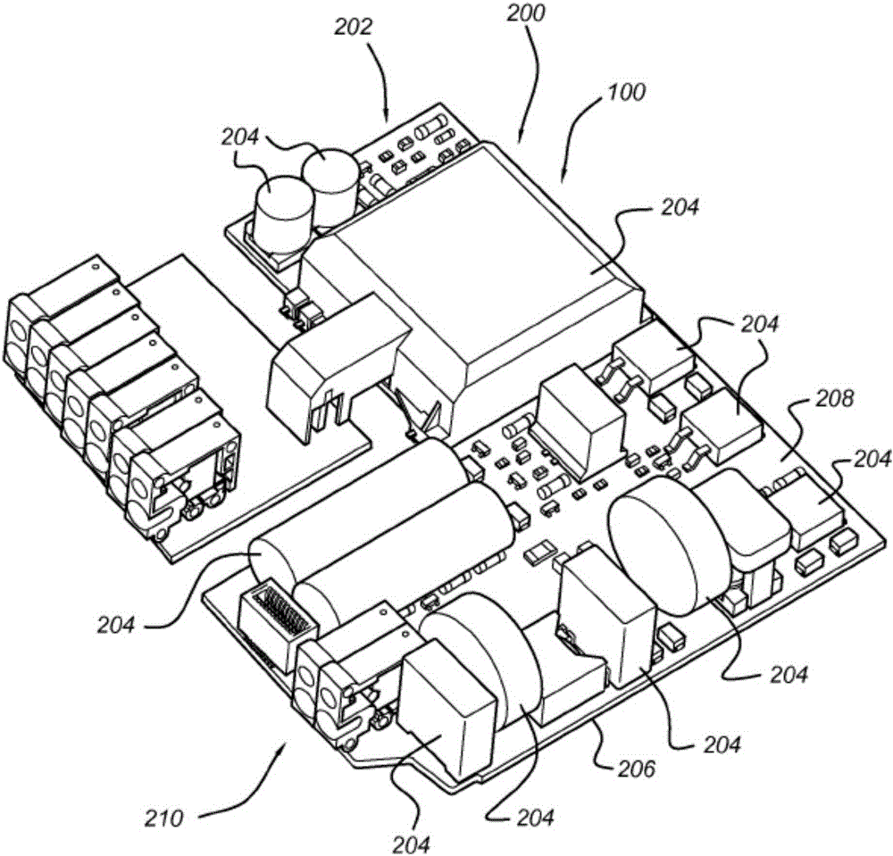
[0084] figure 2 An exemplary embodiment of a power supply element 200 of an electrical assembly 100 is shown. In this exemplary embodiment, the power supply element 200 is a switching power supply 202 .

[0085] In this exemplary embodiment, the power supply element 200 includes a plurality of electrical elements 204 disposed on a carrier 206 . In the exemplary embodiment, the plurality of electrical components 204 are interconnected in a corresponding manner.

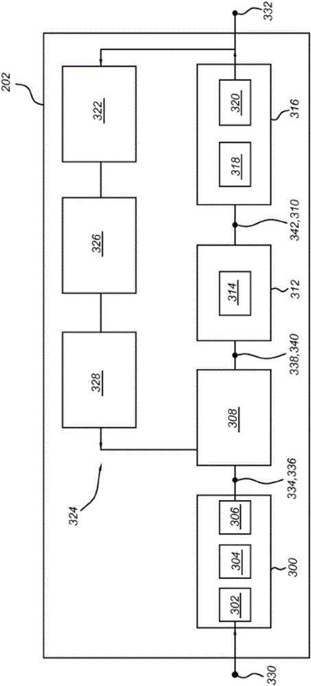
[0086] image 3 Illustrative embodiments of switching power supply 202 design principles are shown. The switched mode power supply 202 has a power connection 330 for connectio...


PUM


Abstract

The invention relates to a switch mode power supply (202) comprising a switch element (308) comprising an NPN-bipolar transistor (402) and a self-conductive field effect transistor (404). Said bipolar transistor (402) and the field effect transistor (404) are connected to form a cascode (400). A bipolar transistor (402) is electrically connected to a winding (502) of a transformer (504), and an additional winding (508) of the transformer (504) is electrically connected to a base connection (408) of the bipolar transistor (402).

Description

technical field [0001] The invention relates to a switching power supply. Background technique [0002] Switching power supplies have switching elements for chopping the rectified and possibly smoothed voltage prior to transformation. The chopped voltage is further rectified after transformation and can also be further smoothed. [0003] A single switch or multiple parallel switches used as voltage switching elements for DC voltages in the range of 100-1000V are high-voltage switches. All kinds of Metal Oxide Semiconductor Field Effect Transistors (MOSFETs), Insulated Gate Bipolar Transistors (IGBTs) and bipolar transistors can be used for this purpose. However, when modern high-voltage MOSFETs operate in the switching frequency range of 20-200kHz, their switching losses and line losses increase significantly with the increase of frequency. Contents of the invention [0004] Therefore, the object of the present invention is to provide a switching power supply with less ...

Claims


Application Information

Patent Timeline
IPC IPC(8): H03K17/0424H03K17/10H03K17/567H03K17/687
CPCH03K17/0424H03K17/107H03K17/567H03K2017/6875Y02B70/10H02M3/158H02M3/335H02M1/0054
Inventor 哈特穆特·亨克尔迈克尔·海涅曼吉多·雷默特
Owner PHOENIX CONTACT GMBH & CO KG
Why Eureka
Try Eureka