Visual electronic stethoscope based on mems acoustic sensor

An acoustic sensor and stethoscope technology, applied in stethoscope and other directions, can solve problems such as affecting the judgment of doctors, comprehensive consultation of unfavorable conditions, complex sound waveforms, etc., and achieve the effect of real and effective signal acquisition, suitable for mass production, and accurate heart rate detection.

Active Publication Date: 2017-10-31
ZHONGBEI UNIV
View PDF10 Cites 2 Cited by
  • Summary
  • Abstract
  • Description
  • Claims
  • Application Information

AI Technical Summary

Problems solved by technology

[0003] The stethoscope was first invented by the French doctor Reynach, and it has been continuously improved to form the traditional acoustic stethoscope that is now commonly used. The traditional stethoscope is composed of a resonance plate, a sound resonance cavity and a sound-conducting catheter. Although the traditional stethoscope is widely used, it is in Some problems were found during use: 1) The sound signals such as heart sound signal and breath sound are extremely weak, difficult to capture, susceptible to environmental interference, and poor in accuracy; 2) The sound waveform is complex, and distortion will occur during transmission. Stethoscope hose The longer it is, the more likely it will be distorted, and it will be limited by the innate hearing of the human ear; 3) It can only be auscultated by one doctor at a time, which is not conducive to the comprehensive consultation of the disease; 4) Doctors often need to calculate heart rate during auscultation, So it must be done with the help of a watch or other timing tools
The above-mentioned shortcomings eventually lead to doctors being unable to make correct judgments in time
[0004] At present, the stethoscope is an in-ear design, and there will be a stethoscope effect during auscultation, which will affect the doctor's judgment and reduce the accuracy of auscultation

Method used


Image

  • Visual electronic stethoscope based on mems acoustic sensor
  • Visual electronic stethoscope based on mems acoustic sensor
  • Visual electronic stethoscope based on mems acoustic sensor

Examples


Embodiment Construction

[0020] The present invention will be further described below in conjunction with accompanying drawing:

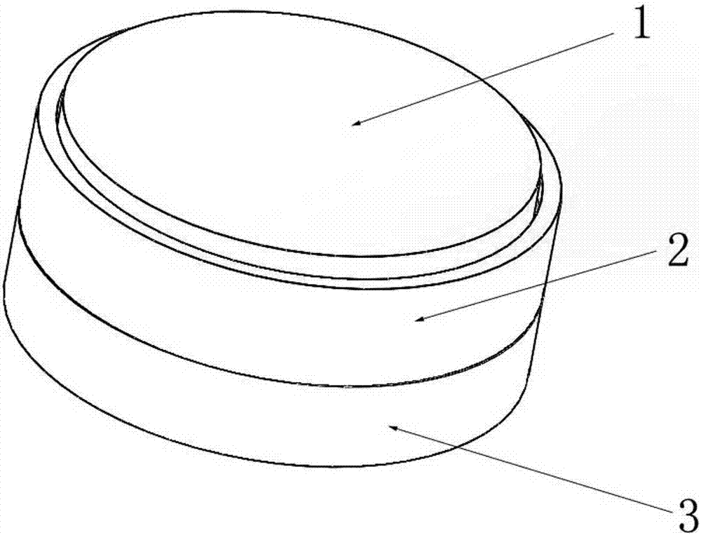
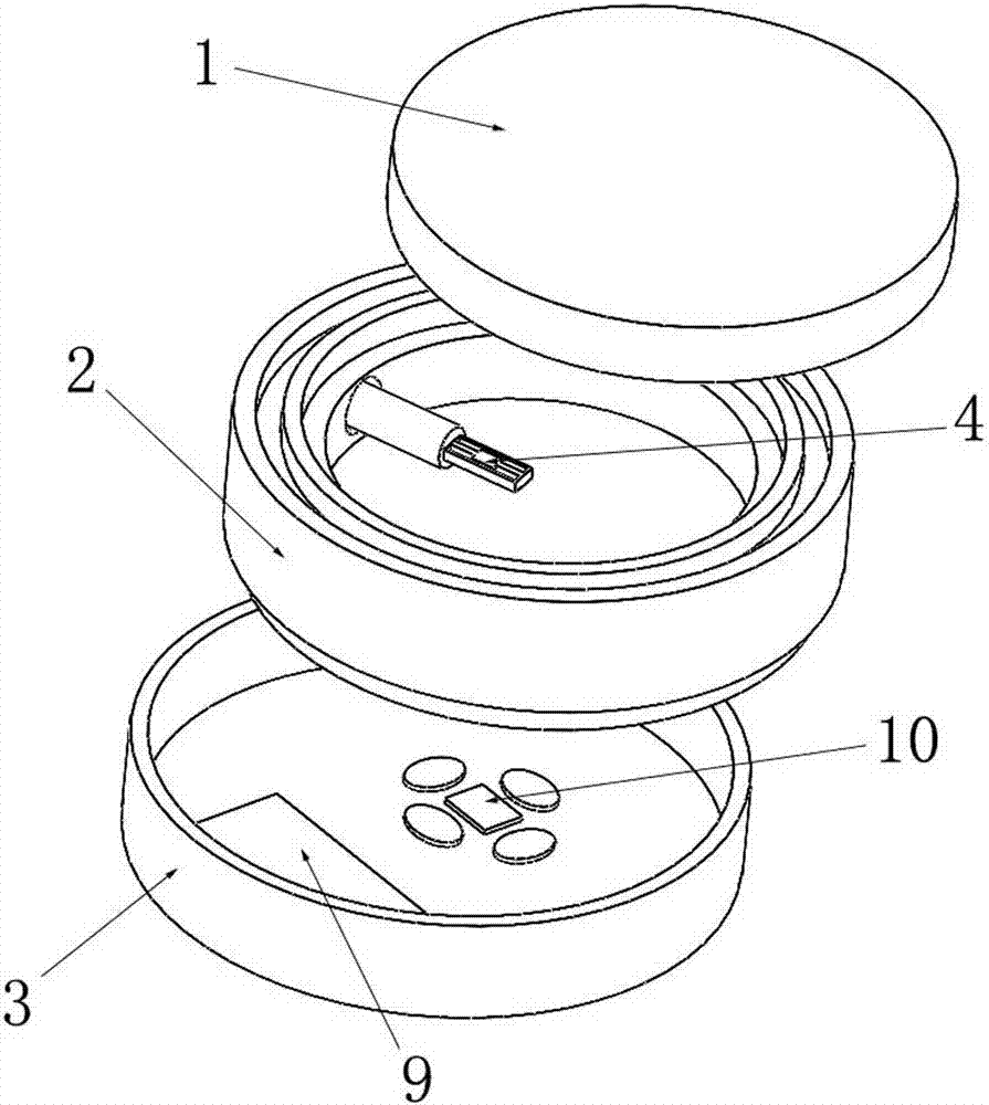
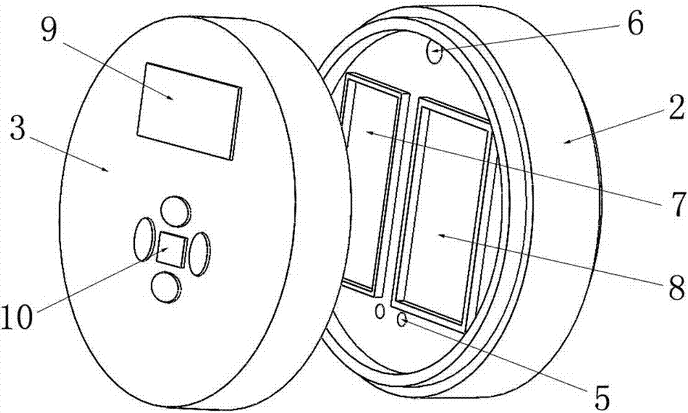
[0021] Such as Figure 1 to Figure 6 As shown, a visual electronic stethoscope based on MEMS acoustic sensor includes a polyurethane sound-permeable cap 1, a housing 2 and a cover 3; Sealed and fixed; MEMS acoustic sensor microstructure 4 is fixed in the inner cavity of the shell 2, an oil injection hole 5 and a lead hole 6 are opened on the shell bottom of the shell 2, and a signal processing circuit is provided on the outer surface of the shell bottom of the shell 2 The board compartment 7 and the lithium battery compartment 8; the cover body 3 is fixed on the bottom of the housing 2, and the cover surface of the cover body 3 is provided with a liquid crystal display 9 and several function selection buttons 10; the processing material of the MEMS acoustic sensor microstructure 4 It is an SOI silicon wafer, which is processed by MEMS semiconductor micromachining technolog...


PUM


Abstract

The invention provides a brand-new electronic stethoscope, specifically a visual electronic stethoscope based on MEMS acoustic sensors, which includes a polyurethane sound-permeable cap, a shell and a cover, the shell is filled with insulating silicone oil, and MEMS is fixed inside the shell The microstructure of the acoustic sensor is filled with insulating silicone oil. The outer surface of the shell bottom is equipped with a signal processing circuit board compartment and a lithium battery compartment. The cover is equipped with a liquid crystal display and several function selection buttons. There is a signal processing circuit board, each control module is arranged on the signal processing circuit board, and the signal processing circuit board is connected with the liquid crystal display screen and the MEMS acoustic sensor microstructure. The stethoscope of the present invention has the advantages of small size, visualization, sensitive detection, low cost, batch processing, and wireless transmission to a computer terminal for displaying waveforms, and is more accurate, more intuitive and more convenient than traditional stethoscopes in detecting heart rate.

Description

technical field [0001] The invention relates to a biomedical device, in particular to a visual electronic stethoscope based on a MEMS acoustic sensor. Background technique [0002] Heart sound and breath sound are two important physiological signals of the human body: heart sound is the general term for the sound produced by the mechanical movement of the heart and cardiovascular system, which contains the physiological and pathological information of each part of the heart itself and the interaction between them; breath sound is the sound of breathing The general term for the sounds produced by the system during the ventilation movement, which contains the physiological and pathological information of the lungs; at present, the main clinical diagnostic method for cardiovascular, cerebrovascular and respiratory diseases is still the auscultation of heart sounds and breath sounds. [0003] The stethoscope was first invented by the French doctor Reynach, and it has been contin...

Claims


Application Information

Patent Timeline
Patent Type & Authority Patents(China)
IPC IPC(8): A61B7/04
Inventor 张国军郭楠曾瑞王续博刘梦然张斌珍薛晨阳张文栋
Owner ZHONGBEI UNIV
Why Eureka
Try Eureka