
Novel gas-blowing gun

An air blowing gun and a new type of technology are used in cleaning methods, spraying devices, liquid spraying devices and other directions using gas flow, which can solve the problems of cumbersome transportation of workpieces, time-consuming and laborious safety, etc., and achieve simple and reasonable equipment structure. The effect of high work efficiency

Inactive Publication Date: 2016-01-13
CHONGQING RUIJIA MACHINERY CO LTD
View PDF7 Cites 5 Cited by
  • Summary
  • Abstract
  • Description
  • Claims
  • Application Information

AI Technical Summary

Problems solved by technology

[0006] The purpose of the present invention is to provide a new type of air blowing gun to improve the existing single structure of the new type of air blowing gun, which leads to complicated transportation operations, time-consuming and laborious work, and low safety problems.

Method used


Image

  • Novel gas-blowing gun
  • Novel gas-blowing gun
  • Novel gas-blowing gun

Examples


Embodiment 1

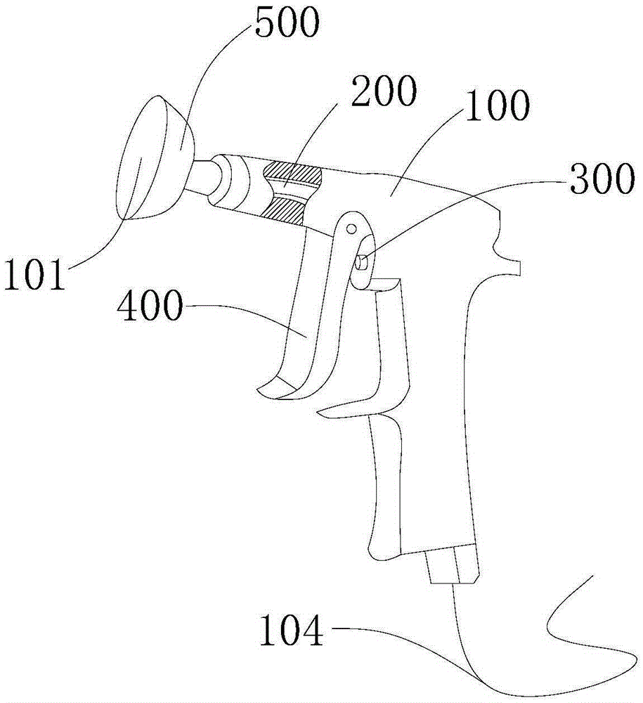
[0050] see Figure 1-3 , the embodiment of the present invention provides a new type of air blow gun, including a casing 100 and a switch assembly, wherein:

[0051] The casing 100 is provided with an air pipe 200, the air pipe 200 includes an air inlet and an air outlet, the air inlet is connected to the air compressor through the bellows 104, and the air outlet is located at the air outlet of the casing 100 The switch assembly includes a valve 300 and a handle 400 connected to the valve 300, the valve 300 is located in the casing 100, and the valve 300 communicates with the air pipe 200; the handle 400 is installed on the machine On the shell 100, the opening of the valve 300 is controlled by pressing the handle 400;

[0052] The novel air blow gun also includes a bowl-shaped windshield 500, the windshield 500 is positioned at the air outlet end of the casing 100, and the windshield 500 is detachably connected to the casing 100, and the windshield 500 The recessed portion ...

Embodiment 2

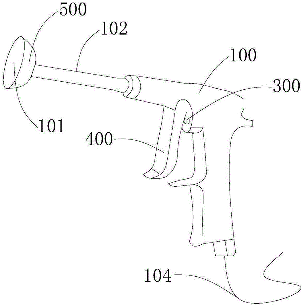
[0061] see Figure 4-6 , this embodiment also provides a new type of air blow gun, this embodiment is a further improvement on the basis of the technical solution in the first embodiment, the technical solution described in the first embodiment is also applicable to this embodiment, the description in the first embodiment The technical solution will not be described repeatedly, as follows:

[0062] The first rod part 201 is inserted into the second rod part 202, and the first rod part 201 and the second rod part 202 are connected by threads; the first rod part 201 includes a threaded rod part 302 and a straight rod part 301 , the threaded rod part 302 is screwed to the second rod part 202 , and the outer diameter of the straight rod part 301 is the same as the outer diameter of the second rod part 202 . The length of steel pipe 102 is adjusted accordingly according to needs, and it is more convenient to use. In some areas with large depth, the length of steel pipe 102 can be ...


PUM


Abstract

The invention provides a novel gas-blowing gun, and belongs to the field of mechanical processing auxiliary equipment. The novel gas-blowing gun comprises an enclosure and a switching assembly, and further comprises a bowl-shaped air cover, wherein a gas tube is arranged in the enclosure; the gas tube comprises a gas inlet and a gas outlet; the gas inlet communicates with an air compressor through a corrugated tube; the gas outlet is positioned in a gas outlet end of the enclosure; the switching assembly comprises a valve and a handle connected with the valve; the valve is positioned in the enclosure; the valve communicates with the gas tube; the handle is mounted on the enclosure; the opening of the valve is controlled by pressing the handle; the bowl-shaped air cover is positioned at the gas outlet end of the enclosure; the air cover is detachably connected with the enclosure; a sunken part of the air cover is sunken towards a tail-end direction of the enclosure along the gas outlet end of the enclosure. When the gas-blowing gun works, a clearing area is wide, and the working efficiency is improved; meanwhile, the novel gas-blowing gun is convenient for clearing different regions, and is convenient and quick in operation.

Description

technical field [0001] The invention relates to the field of mechanical processing auxiliary equipment, in particular to a novel air blow gun. Background technique [0002] During the machining operation, the processing of parts requires chipping and other processes. After cutting, a lot of impurities such as iron chips and plastic chips are produced. These impurities are small in size and large in number. If they are not cleaned in time, they will accumulate in large quantities on the machine tool. , stuck in the gap of the machine tool, causing the machine tool to not operate normally. At the same time, there is a large amount of iron filings scattered on the ground, which is easy to nail the feet of workers, and there is a greater safety risk. In order to ensure the working environment of the machine tool and reduce the accident rate during the machining process, it is necessary to deal with impurities such as iron filings and plastic scraps, and the commonly used air bl...

Claims


Application Information

Patent Timeline
IPC IPC(8): B05B1/00B05B9/01B08B5/02
CPCB05B1/005B05B9/01B08B5/02
Inventor 刘自力
Owner CHONGQING RUIJIA MACHINERY CO LTD
Learn More